Identifying Japanese Jets Captured by the US in 1945
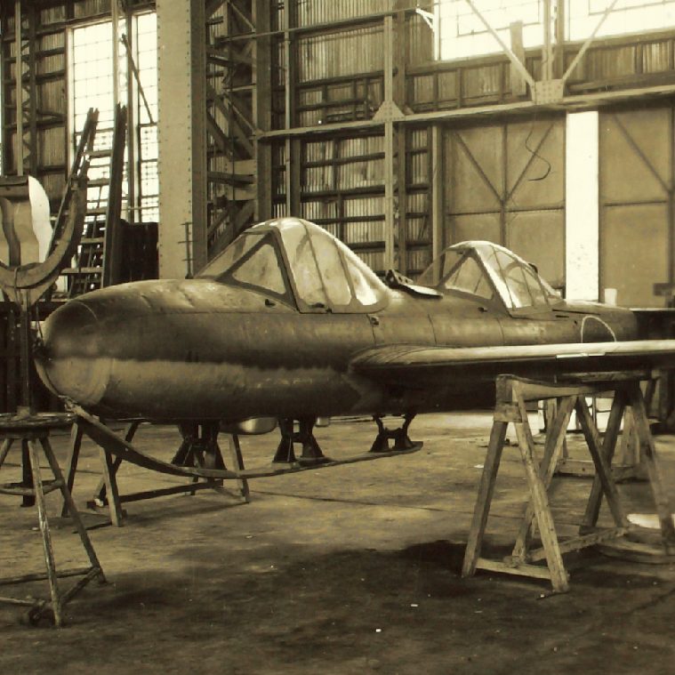
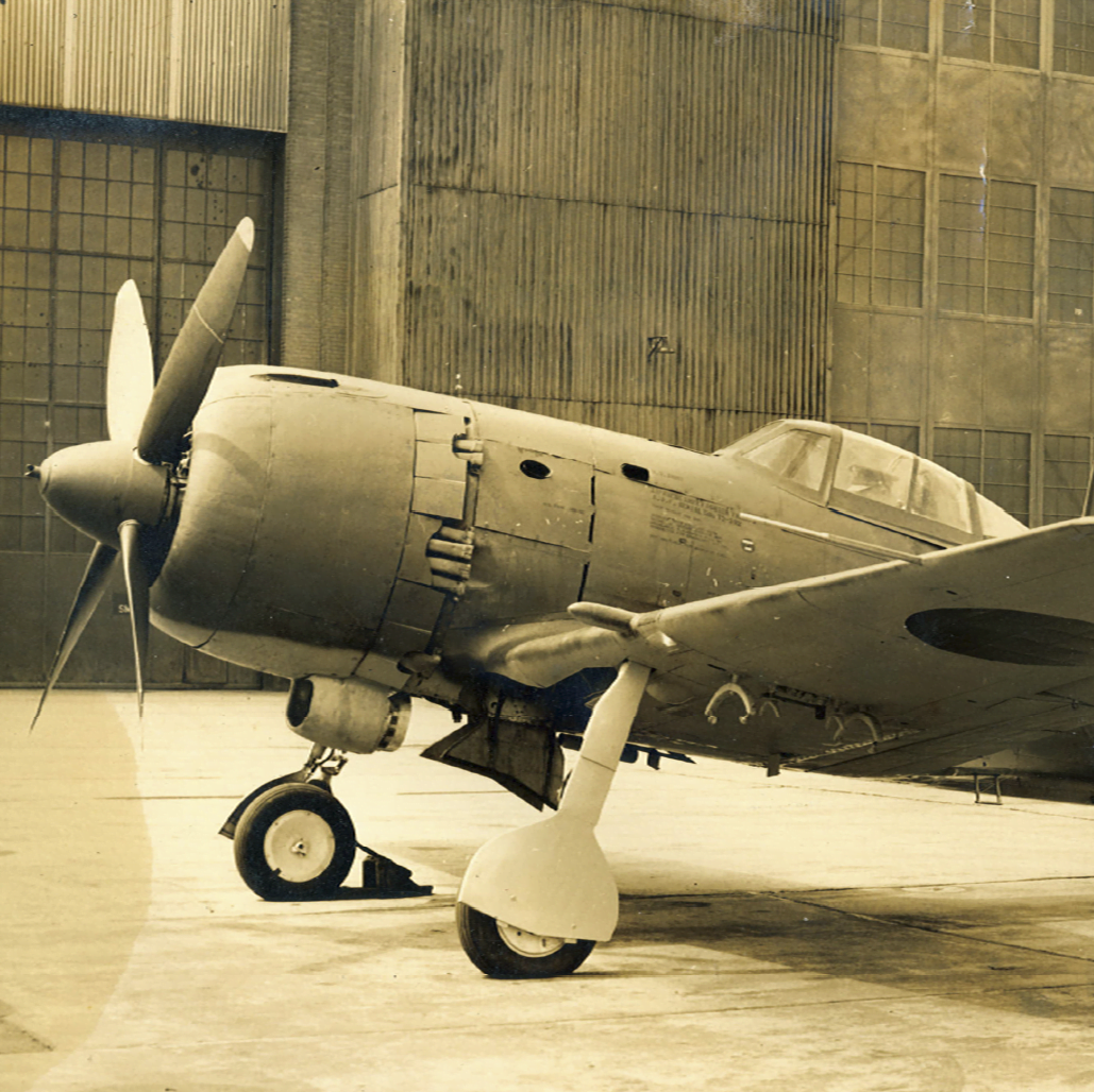
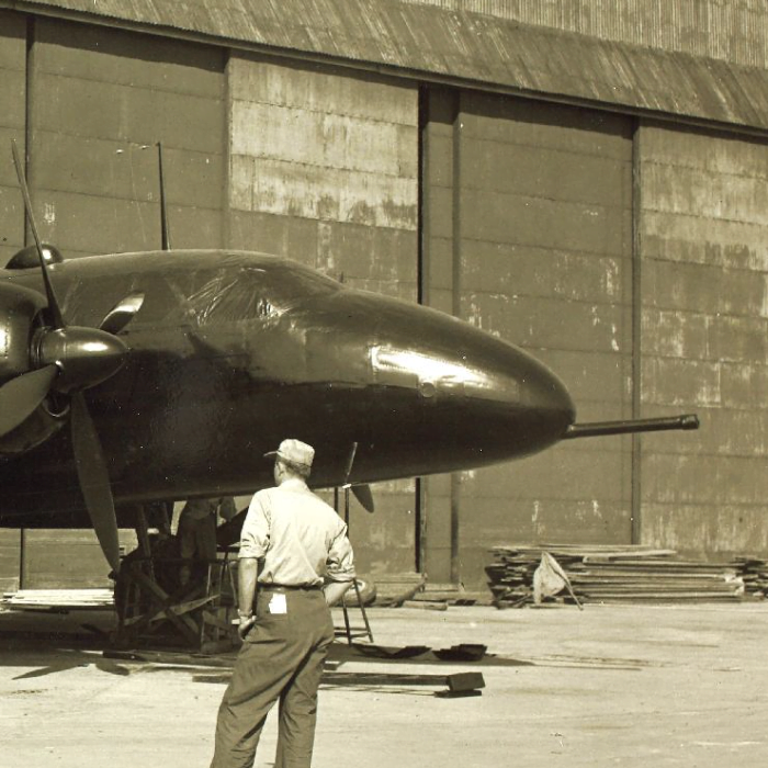
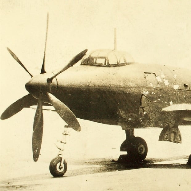
Following the surrender of Japan in August 1945, the American occupational authorities sought to gather whatever aircraft developments were of potential interest. Naturally, the most cutting edge planes and engines developed in Japan were high on this list. More than a few of these projects had already been destroyed by Japanese orders immediately issued to…