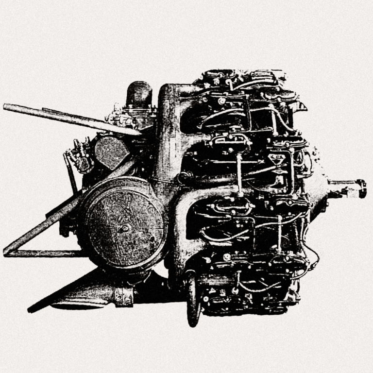
The Uprating Capacity of the Ha-45 / Homare Engine
It is well established that the performance of Japanese aircraft engines in WWII was limited by the suboptimal fuels available at the time, among other factors. As a result, in order to achieve boost pressures in the ballpark of high-power Allied engines, it was necessary to rely on water injection even at nominal operation. Nonetheless,…