
October 15 1945
Ōta Arrangement Department Technical Section
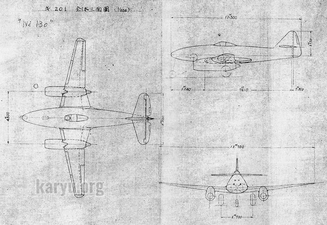
Ki-201 Specification Table
| Category | Value | Category | Value | ||
|---|---|---|---|---|---|
| Dimensions | Model Type | Turbine Rocket Twin-Engine Single-Seat Land-based Fighter-cum-Attacker | Engine | Name | Ne-230 Turbine Rocket |
| Full Width | 13.700m | Performance | Maximum Thrust 885kg (H=0 V=0) | ||
| Full Length | 11.500m | Full Length | 3.410m | ||
| Full Height | 4.050m | Full Width | 0.762m | ||
| Main Wing Area | 25.0m2 | Full Height | 0.950m | ||
| Aspect Ratio | 7.5 | Weight (Bare) | 810 kg | ||
| Aileron Area | 2 x 0.625m2 | ||||
| Vertical Tail Area | 3.074m2 | ||||
| Horizontal Tail Area | 5.288m2 | ||||
| Wheel Interval | 2.700m | ||||
| Ground Contact Angle | 13° | ||||
| Category | Value | Category | Value | ||
|---|---|---|---|---|---|
| Performance | Maximum Speed | V=792km/h H=6,000m | Weight & Center of Gravity | Empty Weight | 4465kg |
| ^ | V=812km/h H=10,000m | Loading Weight | 2497kg | ||
| Climbing Time | T=10’18” H=8,000m | Normal Load | 6962kg 25.3% | ||
| Maximum Climb Rate | 18.9m/s H=0 | Overload | 8469kg 30.2% | ||
| Ceiling | 13,600m | Full Height | 0.950m | ||
| Cruising Range (Normal) H=8000 | Thrust 100% V=810: 794km 80% V=709: 888km 60% V=579: 979km | Result | Basic design started in January 1945 50% of the design completed at the end of the war | ||
| Landing Speed | V=158.5km/h | ||||
| Takeoff Distance | 478m | ||||
| Equipment | 20mm Machine Cannon | 2 | |||
| 30mm Machine Cannon | 2 | ||||
| Special Equipment (1) Bomb | 800kg (or 500kg) x 1 | ||||
| ^ (2) Drop Tank | 600l x 1 | ||||
Structure
1. Outline
The emergence of turbine rocket aircraft as new weapons was seen during the current Great War, and they proved to be advantageous operationally due to outstanding high speed, as well as in mass production of the turbine rocket engine.
This plane is a special weapon; a twin-engine single-seat land-based fighter-cum-attacker equipped with Ne-230 turbine rockets. A low-wing monoplane semi-monocoque stressed-skin structure is used together with light alloy and steel.
2. Main Wing
It consists of a mid-wing and outer wing, which are joined by bolting together the main spar, auxiliary spar, stringers, and longerons. The mounting angle is 3°, the wing-fuselage joint is easy to separate, and at the sidewall of the fuselage, the main spar, auxiliary spar, and stringers are joined with the round frames by bolts.
a. Mid Wing
It is a stressed-skin semi-monocoque with a single spar structure. It is laterally unified by an auxiliary spar. The spar is web-plate type, the stringers are H.D.T. extruded profiles, the web-plate uses SDH, and the skin, longerons, and ribs also use SDH.
The inner slotted flaps and leading-edge slats are installed to the mid-wing section, the inner-fuselage-retracting main wheel landing gear is located between the spars, and the turbine rocket is mounted outside of that on the wing underside via a vibration absorber. The wing thickness is a constant 13%.
b. Outer Wing
It has both a main and auxiliary spar, and at the wing joint it is semi-monocoque, but it becomes pure monocoque near the aileron. The structure and materials used for the spar are the same as the mid-wing spar, and the auxiliary spar and stringer material is silicon manganese steel.
The skin and longerons are made of SDH, and all the ribs use tin plate or carbon steel plate. The outer wing is equipped with a slotted flap, aileron (aileron flap), winglet, and a leading-edge slat that is partitioned to the inner and outer. The wing thickness ranges from 13% to 9%, and it has a 2.5° washout.
3. Fuselage
The fuselage consists of 3 sections; the front, middle, and rear, and all parts are joined together by many small bolts. Each section is stressed-skin semi-monocoque, and the cross-sectional shape is circular at the tip but becomes triangle-shaped above the rear of the wheel storage. It changes to an elliptical shape near the vertical stabilizer. The maximum width is 1.8 m.
a. Front Fuselage
For the front undercarriage and gun installation, there are undercarriage mounting sidewalls, and gun mounting beams and floor. Also, there are magazine covers and an undercarriage strut/wheel cover installed. The skin and main round frames are made of SDH, the general round frames, longerons, sidewalls, beams, and the floor use tin plate, and the main longerons are made of silicon manganese steel.
b. Mid Fuselage
There is a cockpit in the center, 1200 l main fuel tanks in front and behind it, and a 600 l auxiliary fuel tank behind the rear main fuel tank. The cockpit floorboard is supported by central ribs and uses tin plate. The main wheels are stored under the floor.
SDH is used for the skin, longerons, and round frames, and tin plate is used for the firewall. The front and rear fuel tanks as well as the motor-cock chamber cover use SDH.
The cockpit windshield has an SDH frame and is rearward-sliding open/closing type.
c. Rear Fuselage
The radio and radar are housed in the front of the rear fuselage, and there are lug fittings for installing the tail and work ports.
SDH is used for the skin and particular round frames, tin plate is used for the general round frames, and silicon manganese steel is used for the longerons.
4. Tail
a. Horizontal Stabilizer
It is laterally unified and has a twin-spar stressed-skin structure. The leading edge is covered. Designed to allow fitting of a mounting angle adjustment device. The skin, web-plate, and longerons use SDH, the spars and stringers use SDH extruded profiles, and the ribs excluding the central ribs use tin plate. Fh=4.113 m2.
b. Elevator
The mover has a metal, cloth-covered structure and a trim tab made of SDH. It also has a horn balance made of cast iron. The leading edge skin, and the ribs and spar of the same use tin plate or carbon steel plate, and the trailing edge ribs use SDH to reduce weight. The rudder angle is 30° raised and 20° lowered, and reaches 70% during rapid rudder angle adjustment. Fe=2×0.588 m2.
c. Vertical Stabilizer
It has a twin-spar stressed-skin structure and the leading edge is covered. The materials used are the same as the horizontal stabilizer. The mounting angle is zero degrees. Fv=2.018 m2.
d. Rudder
It has the same structure as the elevator and has a trim tab. The rudder angle on both the left and right is 30 degrees, and there is no rapid rudder angle adjustment device. Fr=1.056 m2.
5. Aileron
The skin of the leading edge has a metal cloth-covered structure, the ribs, and spar of the same use tin plate or carbon steel plate, and the trailing edge ribs use SDH. Acts as an aileron flap in conjunction with the leading edge slat during landing. The rudder angle is 20° raised and 25° lowered. The rudder angle as an aileron flap is 15°.
6. Wing Flap
It is a slotted flap consisting of an inner and outer flap. The inner flap is between the fuselage and the rocket, the outer flap is between the wing joint section and the aileron. The operation is hydraulic, the inner and outer on the left and right side operate together, the operation angle is 20° when taking off and 40° when landing.
It is a single-spar type stressed-skin structure, and the upper surface behind the spar is covered in cloth. SDH is used for the leading edge skin and spar, and the rest uses tin plate.
7. Landing Gear
The front-wheel format was adopted.
a. Main Undercarriage Assembly
The main undercarriage assembly mainly uses silicon manganese steel and is attached via the mid-wing undercarriage mounting beam and auxiliary spar. Operation is hydraulic, it is link retracting type, and the wheels are stored inside the fuselage. It has air hydraulic shock absorbers, and the inner diameter of the oleos is 200 mm. The wheels are 5 atmospheres and 950×320 mm. The undercarriage struts and wheel covers are made of SDH.
b. Front Undercarriage Assembly
The front undercarriage assembly is also mainly made of silicon manganese steel and is attached to the front fuselage undercarriage mounting wall. It has an air hydraulic shock absorber, the oleo inner diameter is 80mm, and the stroke is 250 mm. The wheel is 4 atmospheres and 600×175 mm. Operation is hydraulic, the wheel is retracted in conjunction with the main undercarriage, and the undercarriage strut and wheel cover is made of SDH. Additionally, it has a hydraulic vibration absorber and also has an emergency lowering device.
8. Turbine Rocket Mounting and Cover
The rocket is mounted to a metal bracket installed on the leading edge of the mid-wing and the ribs via rubber and bolts. The cover consists of three parts, front, middle, and rear, and uses SDH.
The front cover is double-walled, the inner wall acts as the “diffuser” wall, and a 50 l oil tank and oil cooler are stored between the inner and outer walls. Furthermore, there is an inspection cover on the upper side, for inspecting and servicing rocket auxiliary equipment. The middle cover is made up of the left and right parts, and the turnbuckle is tightened to free it from the main wing. This section bears the axial compressor and combustion chamber. The rear cover also consists of two parts on the left and right and is free from the main wing. This section bears the airflow-rate adjustment valve and an exhaust section.
Airframe Equipment
1. Armament
Two 20 mm and 30 mm machine cannons each are equipped in the upper part of the front fuselage, and magazines are mounted to the sidewall of the undercarriage, arranged on the underside of the floor between the fuselage walls. Empty cartridges and ammo clips are all stored.
The 20 mm machine cannons are placed above and inward and carry 2 x 200 rounds of ammo.
The 30 mm machine cannons are placed below and outward and carry 2 x 120 rounds of ammo.
Loading is hydraulic, firing is electrical, and all cannons are loaded and fired simultaneously.
2. Bomb Equipment
A suspension beam can be mounted below the fuselage to equip 1 500 kg or 800 kg bomb. The suspension beam is easy to attach and detach, and the bomb drop is manual.
3. Bulletproof Equipment
70 mm of bulletproof glass is used on the front fixed windshield, an 8 mm bulletproof steel plate is installed ahead of the seat, 12 mm at the head, and 8 mm at the back. Each fuel tank is coated with 10 mm of bulletproof rubber, and the main fuel tank chambers are provided with extinguishing fluid equipment.
4. Communication and Radar
The radio is stored in the rear fuselage immediately after the mid-fuselage, a Ta-Ki Mk.15 friend and foe identifier is installed behind the seat, and a Ta-Ki Mk.13 altitude indicator is in the rear fuselage near the radio.
5. Oxygen Equipment
Two 3.3 l oxygen “bombs” are installed in the front fuselage, and 3 chemical oxygen generators are near the rear fuselage work ports.
6. Auxiliary Powder Rocket Equipment
Two 1000 kg powder rockets are installed on the left and right of the underside of the fuselage for takeoff.