It is well established that the performance of Japanese aircraft engines in WWII was limited by the suboptimal fuels available at the time, among other factors. As a result, in order to achieve boost pressures in the ballpark of high-power Allied engines, it was necessary to rely on water injection even at nominal operation.
Nonetheless, aviation enthusiasts often speculate on the performance of Japanese aircraft if they were supplied with high-octane fuels and up-rated appropriately. This is partially due to the fact that there are widespread myths of superior performance numbers being achieved with Japanese aircraft using American high-octane fuel, when in reality, in most if not all cases these numbers are wartime calculations using inadequate data.
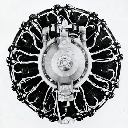
Homare
Nonetheless, it is an interesting question. In a past article on the Ki-84, I wrote that “it’s unknown how much additional pressure a Japanese mass-produced Ha-45 could even handle.” Thanks to an article I recently read in the book「日本航空学術史 1910-1945」(Aeronatical Researches in Japan 1910-1945), there is a satisfactory answer to this.
Single-Cylinder Test Units
From April 1939 to March 1944, the Engine Department of the Navy Aviation Technical Arsenal (Kūgishō) manufactured single cylinder testers and conducted tests on the power enhancement of aircraft engines using these machines.
In the past, these experiments relied on foreign imported single-cylinder testers manufactured by the American SPE Company (Self-Priming Pump and Engineering Company) and the German DVL (Deutsche Versuchsanstalt für Luftfahrtforschung). However, this posed a problem when experiments resulted in a broken part of the test units, as they were not domestically produced.
To solve this problem, it was decided to manufacture a domestic single-cylinder tester that could use Japanese mass-produced engine components. The single-cylinder tester was to have easily changed experimental parameters and be able to withstand harsh operation.
For changing the engine compression ratio, the DVL method was adopted in which the engine cylinder mounting base could be vertically adjusted with a handle. An SPE type balancing rod was used to manage the balancing of dynamic forces at high operating RPM. The valvetrain was designed so that it could be adjusted with a dolly lever so the angle of the valves and pushrods would not have to be changed according to whichever cylinder of an actual engine was installed, and the cams and dolly levers could be made to match each engine. Crankshafts were made in several different strokes with a shared diameter. The auxiliary shaft had a large amount of attachment points so that many engine accessories could be installed.
About 20 units were manufactured in total, with examples made for the Homare, Kinsei, Amakaze, and Kamikaze engines. These single-cylinder testers were distributed to fuel depots and the Central Aviation Research Institute. Later models were being developed for water-cooled engines and prototype engines, but were not completed due to the deteriorating war situation.
Power Enhancement Tests
For tests on enhancing the power of engines, the Kinsei and Homare units were chiefly employed. Various factors would be adjusted individually to increase power output such as the compression ratio, RPM, boost pressure, air/fuel mixture, ignition timing, and type of fuel. The results of testing were plotted on a graph with power as the horizontal axis and cylinder temperature as the vertical axis. The objective was to increase power with as little rise in cylinder temperature as possible, so a shallow curve was desired. Generally speaking, the most promising results were achieved by increasing the RPM or boost pressure.
With the Homare test unit, a two-stage roots supercharger with a supercharging capacity of up to +1500 mmHg boost (2.974 atm, 88.98 inHg) was attached, and tests were conducted using highly detonation-resistant fuel consisting of iso-octane mixed with 0.15% tetraethyl lead, benzol, toluol, and other aromatics, in conjunction with water-methanol injection. It was confirmed that the Homare could withstand being supercharged up to about +800 mmHg (2.053 atm, 61.42 inHg). This is the mechanical limitation of the engine.
As designed, the nominal operating boost pressure of the Homare Model 21 / Ha-45 engine was +350 mmHg (1.461 atm, 43.70 inHg), or +500 mmHg (1.658 atm, 49.61 inHg) at takeoff/emergency operation.
This is an update to the previous article about the performance of the Type 4 Fighter (Ki-84), addressing some errors and new information that I have found since writing it.
It is not so much an article as a set of separate points.
The engine fitted to the first three prototypes of the Ki-84 was designated the “Ha-45 Special” by the Japanese Army. Despite the name, it is in fact an inferior engine to the “Ha-45” (Ha-45-21). The “Ha-45 Special” is a Ha-45-10 series engine.
In the first article, I wrote that the “Ha-45 Special” was the Ha-45-12. In fact, it seems that the Ha-45 Special was actually the Ha-45-11. This is stated in the document「発動機名称一覧表」[Engine Designation List] created by the Navy Aviation Headquarters on April 11, 1945.
This is further supported by the document “Specifications of Special Army Planes” created by the Army Aviation Examination Dept on August 1, 1943. Here, the projected performance of Ki-84 is written to be 660km/h at 5700 meters, which is the critical altitude of the Ha-45-11. This document was captured and translated by the United States, and the relevant page is pictured below.
This is an important distinction, because the Ha-45-11 and Ha-45-12 have different altitude performance. The supercharger’s first and second speeds were stepped up 5.47⇒5.81 and 7.49⇒7.95, respectively, in the Ha-45-12. This raised the second speed critical altitude from 5700m to 6550m. Below is an excerpt from the Homare manual showing the specifications of the Model 11, 12, 21, and 22, as of December 1943.
It appears to check out that the initial prototypes were equipped with the Ha-45-11. The official performance of the Ki-84, which originates from a test with one of these prototypes, shows that the top speed was achieved at 6550 meters. This indicates that the critical altitude of the engine was increased by perhaps 850 meters due to ram pressure at the Ki-84’s top speed. It would make less sense if this plane was using a Ha-45-12, because that would indicate that there was no increase in the critical altitude from ram pressure.
Furthermore, we can see in the climb test obtained from the same aircraft that the engine began to lose manifold pressure just before 6000 meters when flying at low speed.
Ki-84 Prototype vs. Service Plane
The performance achieved by a Ki-84 prototype is considered to be the “official performance” of the Ki-84, and is written in its piloting manual. However, knowing that the Ki-84 prototype probably used a Ha-45-11 engine, we would expect the performance of a service plane to actually be somewhat different.
Mass production examples of the Ki-84 that were put into service used a Ha-45-21 engine (which the Japanese Army simply called Ha-45, or Type 4 1850 HP Engine). The Ha-45-21 was restricted to prevent engine failures, as is well known. The RPM was limited to 2900, and the manifold pressure to +250mm, just like that of the 10 series engines. With this, the critical altitude rose to about 6500m, which is essentially the same as the Ha-45-12.
Because the Ha-45-21 in its de-rated condition has (on paper) a critical altitude 800 meters higher than the Ha-45-11, as well as 60 more horsepower at critical altitude, we would expect a service Ki-84 to actually have a slightly higher top speed than the 624km/h of the Ki-84 prototype if it was operating in ideal condition.
Every Ki-84 Had Exhaust Thrust
This is not an error with the previous article but an elaboration. It is sometimes said that the early Ki-84s did not generate exhaust thrust. All units of the Ki-84 had exhaust pipes which produced thrust.
The initial prototypes and early pre-production units had a thrust-generating collective exhaust. Later, it was changed to individual thrust-generating exhaust pipes. We can be sure that the thrust force was improved to some extent, but it will not be as marked as the change from standard exhaust pipes to thrust-generating individual exhaust pipes.
For reference, the change from standard (non-thrust generating) exhaust to individual thrust-producing exhaust pipes netted the A6M5 about 10 kts (19km/h) of top speed, with its Sakae 21 engine that provided 980 HP at its top-speed altitude.
The Full-Rated Performance Gap
With a fully-rated Ha-45-21 engine, there exists a record showing a top speed of 634km/h for the Ki-84, which is referenced in the first article.
The idea that the Ki-84 only gained about 10km/h of top speed (624km/h ⇒ 634km/h) when using a “Ha-45” (Ha-45-21) engine seems difficult to believe to some. The fact that the prototype which achieved the lower speed probably had a Ha-45-11, rather than Ha-45-12 engine, makes this performance gap even more egregious.
It is relatively well accepted that the Ki-84’s propeller was inadequately sized for its class of engine, which greatly hindered its ability to make use of greater power. The Ha-45-21 had an increase in output of at least 120 horsepower compared to the Ha-45-12 their critical altitudes. However, the critical altitude of the 21 is about 400 meters lower than that of the 12 (ultimately, it is thought that the critical altitude of the fully-rated 21 was perhaps just 6100 m).
On the other hand, the Ha-45-11 not only has even less power (1440 HP at 2nd speed) than the Ha-45-12, but its critical altitude is lower than even the Ha-45-21, as previously noted. This means that the Ki-84 with a fully-rated Ha-45-21 engine had not only greater power, but at a greater altitude, and still only marked 634km/h.
Additional Evidence for Full-Rated Top Speed
The origin and condition of the fully-rated Ki-84’s 634km/h top speed record has been questioned, and though it is said to be a translated document, there is little contextual information about it.
However, there seems to be additional evidence supporting this fully-rated top speed. This comes from the document「陸軍航空技術沿革史」[History of Army Aviation Technical Development] which was published by the 1st Demobilization Bureau in May, 1947. Though it is post-war, this document was written by former staff of the Japanese Army. Within this document is the table「陸軍制式飛行機諸元表 (A)」[Army Service Airplanes Specification Table (A)].
This table lists performance for both the “Type 4 Fighter (Ki-84I)” and the “Type 4 Fighter Performance Improved“. The engine column shows that the former represents the Ki-84 with a de-rated engine, while the latter represents a plane with a fully-rated engine (referred to here as Type 4 1850HP Kai). These differing names are purely informal.
The top speed listed with the fully-rated Ki-84 is 635km/h at 6400m. The climb time is 5’50” to 5000m.
This compares closely with the values from the other fully-rated test mentioned in the last section, which showed a top speed of 634km/h at 6650m, and a climb time of 5’37” to 5000m.
I believe that 635km/h is a reasonable value for the “true performance” of the fully-rated Ki-84, on rated power. Use of “takeoff power” (essentially war emergency power, WEP) at altitude may have yielded a slightly higher top speed, but not markedly, as the critical altitude would be around 1000 meters lower.
If the Ha-45 engine was able to be produced with a compression ratio of 8.0, as was originally planned, the performance would have been greater, but this was not the case.
(The reduction of the Ha-45-21 CR from 8.0 to 7.2 is most likely the explanation for its fully-rated 2nd-speed horsepower output being reduced from the ballpark of the 1700s to the 1600s).
Expected vs. Achieved Performance
According to the “Famous Airplanes of the World” issue on the Type 4 Fighter, the required top speed issued for the Ki-84 was 680km/h, and the climb time was 4’30” to 5000m.
On the other hand, the “Specifications of Special Army Planes” document shows what seems to be a calculated or required top speed performance of 660km/h, along with the same climb time of 4’30” to 5000m.
Was the requirement reduced to 660km/h? Did Nakajima calculate 660km/h? Or was 660km/h simply the expected performance when equipped with the weaker 10-series engine? The latter would seem to be the obvious guess, but it’s not clear because the climb time remains the same.
If we interpret the expected performance of Ki-84 to be 660km/h, the actual plane seems to have fallen short by about 25km/h. The climb time, more clearly, was more than 1 minute slower than the requirement to 5000m.
Extra Explanation for the Small Performance Gap?
This last section is to be taken less seriously, and is not anything more than an idea. An awfully inadequate propeller could be the sole explanation for the lack of performance in the fully-rated Ki-84.
Anyway, the first prototype of the Ki-84 was initially completed with a smaller 19m2 main wing according to numerous secondary sources, such as the “Famous Airplanes of the World” issue. All subsequent planes had a larger 21m2 main wing, and it seems that the first unit was later modified to use the final wing.
I have not located a source which specifies which of the initial 3 Ki-84 prototypes achieved the 624km/h at 6550m top speed. If we consider the possibility that it could have been the first prototype with its original, smaller wing, it makes sense that the performance gap between this record and the fully-rated, longer-wing Ki-84 would be more negligible in terms of top speed.
It seems unlikely that the 19m2 wing unit recorded this test, however, because this performance was later used as the “official performance” of the Ki-84 in general.
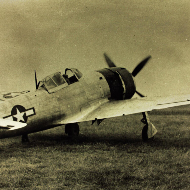
Ki-84 Prototype #1
Sources
Famous Airplanes of the World No. 19: Army Type 4 Fighter ‘Hayate’. Tōkyō: Bunrindo, 2019.
The A6M4 is an “unknown” variant of the Zero Fighter that has been described as a variety of things over the years. The most common theory in English writing is that A6M4 was a designation for a type of Zero fitted with a turbocharger to its Sakae engine. Another common theory is that the number was skipped to avoid using the unlucky number “4”, which can be pronounced the same way as “death” (shi) in Japanese language.
A handful of original Japanese documents exist which can be used to paint a vague outline of what the A6M4 actually was. This article serves as a summary of the various wartime references to an “A6M4”, or otherwise a “Model 40” Zero Fighter, that are known to me.
A6M4 as a Turbocharged Zero Fighter
In the February 1942 Arsenal Gazette of the Navy Aviation Technical Arsenal (Kūgishō), a report dated February 4th outlined a research meeting that was to take place on the 9th of the same month at 15:00. The subject of the meeting was a structural examination of a partially wooden model of a Sakae Model 10 engine fitted with a turbocharger. The purpose was for the eventual installation of a turbocharger in the Zero Fighter.
The next reference in the Arsenal Gazette was dated February 10th, and it outlined the schedule of the first research meeting concerning the fitting of the Zero Fighter with an Ishikawajima turbocharger. This meeting was to take place on the 19th of the same month at 13:00.
It should be noted that these brief meeting schedules did not state which model of Zero Fighter was to be equipped with the turbocharged engine, nor was a designation for this prospective variant given. However, at this time, the engine under examination was a Sakae Model 10-series, which is of the same series as the engine installed in the A6M2.
The next reference to the turbocharged Zero Fighter is more well-known: an English translation of a Japanese document that was captured on Saipan, titled “Quarterly Report on Research Experiments,” and dated October 1, 1942. This is where the first mention of the “A6M4” as a turbocharged Zero variant is known to appear, and the relevant text is in the images below.
Assuming that the translator did not make a typing error (which is more common in translated documents than you may hope), at this time, the “A6M4” was a designation for a development of the A6M3 with an intercooler — almost certainly indicating that it would have a turbocharged engine. The next step in development was for wind tunnel testing to be carried out, according to the record.
We can be fairly sure that this “A6M4” was a development of the A6M3, because it is written under the general section concerning the “Type 0 Mark 2 Carrier Fighter”, which was an earlier designation of the Zerosen Model 32 (A6M3).
On the other hand, Francillon wrote the following entry in his 1967 title “The Mitsubishi A6M3 Zero-Sen (Hamp).”
Francillon stated that Jirō Horikoshi (the head designer of the Zero Fighter) personally informed him that the A6M4 designation referred to two A6M2s that were fitted with a turbocharger in 1943. Unsurprisingly given the situation of turbocharger implementation in Japan at that time, this testing was described as a failure.
Whether it is the case that the turbocharged Zero Fighters were converted from the A6M2 or A6M3, there is reasonable evidence here to state that the “A6M4” designation was most likely applied to the turbocharged Zero Fighter project by late 1942. However, it seems that upon the failure and abandonment of these prototypes, the designation was later re-used for other projects.
Turbocharged Sakae Engine
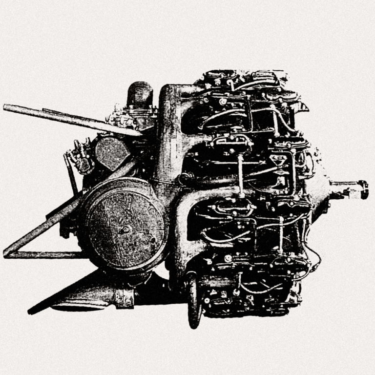
A Sakae Model 11 engine with a wooden mockup of a turbocharger installation attached to it is pictured below. This is likely to be the same model that was examined at the Kūgishō in early 1942. It can be observed that the compact installation model did not actually include an intercooler at this time.
The turbocharger represented by this model was the Ishikawajima Model IET4. The Model IET4 was designed to maintain the full pressurization of the Sakae engine up to an altitude of 7000 meters.
Fake A6M4
The image on the left below is supposed to show an A6M2 with a turbocharger. In fact, to this day it is a top image result when searching online for “A6M4” or “Zero with turbocharger”. However, it’s just a photoshop of an image of a standard A6M2, compositing a picture of the turbocharger from the Army prototype fighter Ki-87.
A6M4 (?) as an A6M2 with Belt-Fed Guns
Another document possibly related to the “A6M4,” titled “Matters Pending Approval Regarding Airplane Remodeling Experiments,” was created on April 28th, 1943. This document shows various tentative decisions regarding aircraft models in development, including future variants of the Zero fighter.
The following relevant text is quoted:
Type 0 Fighter
(a) Zerosen Model 21
Changed 20mm fixed machine gun ammo capacity from 100 rounds per gun to 150 rounds per gun (belt feed). Provisionally designated as Zerosen Model 41 and ordered to Nakajima.
(b) Zerosen Model 22
(1) Changed 20mm fixed machine gun ammo capacity from 100 rounds per gun to 150 rounds per gun (belt feed). (2) Abolished wingtip folding mechanism and shorten wingspan by about 1 meter. Provisionally designated as Zerosen Model 52 and ordered to Mitsubishi.
Therefore, we can say that as of April 28, 1943, it had been tentatively decided to give the designation “Zerosen Model 41” to a Zerosen Model 21 (A6M2) fitted with belt-fed 20mm machine guns. The designation “Zerosen Model 52” was to be tentatively provided to a Zerosen Model 22 (long-wing A6M3) with belt-fed 20mm machine guns and shortened wings.
In the Japanese Navy’s aircraft naming nomenclature at the time, the first numeral of the model number represented airframe modifications, while the second number represented engine modifications. According to this system, the reasoning behind these provisional designations is briefly as follows:
Model 21 + 1 airframe modification (belt-fed guns) ⇒ Model 41 (3_ is skipped because it is occupied by the shortened square wing modification of Model 32).
Model 22 + 2 airframe modifications (belt-fed guns, shortened round wingtips) ⇒Model 52 (3_ is skipped for the same reason as prior, because Model 32 had shortened wings with square wingtips, while Model 52 had round wingtips).
No code names are listed in this document, and just because it was a “Model 4_” Zero Fighter does not mean that it would necessarily be designated A6M4.
Furthermore, there is no known information which would suggest that the Model 41 was ever built. The Model 52, of course, would go on to be mass produced.
However, when the Model 52 was actually adopted into service on August 23rd, 1943, it was recorded that its prior tentative designation had still been the “Type 0 Ship-Based Fighter Model 22 Kai”, as can be seen in the following document (which also shows the adoption of the Gekkō Model 11).
Type 0 Ship-Based Fighter Model 22 Kai (shortened wingtips of main wing) is adopted as a weapon and designated as Type 0 Ship-Based Fighter Model 52.
A6M4 as an Early Name for A6M5
To quickly recap from the previous section, this is what had been tentatively decided as of April 1943:
Model 2X: 12 meter wingspan with folding wingtips.
Model 3X: 11 meter wingspan with square wingtips, no folding mechanism.
Model 4X: 12 meter wingspan (Model 2X airframe) with belt-fed 20mm MGs.
Model 5X: 11 meter wingspan with round wingtips, no folding mechanism, and belt-fed 20mm MGs.
In reality, the belt-fed 20mm MG (that is, the Type 99 20mm Mark 2 Fixed Machine Gun Model 4) was not actually ready in time for the mass production of the Model 52.
So while the Model 5X had been defined as having 2 modifications over the Model 2X, belt-fed 20mm guns (which is what brought it to 4X) and clipped, rounded wingtips, the actual first production Model 52 or A6M5 only had the latter modification.
This is important to consider when looking at the next and final document regarding the A6M4, which is a translated document about aircraft armament, captured on Peleliu. The data comes from a Japanese notebook and was probably created in mid-1944. Here the “Model 42” is listed, with the code name “A6M4” specified.
Above the Model 42 is two Model 52 (A6M5) with differing armaments. The top Model 52 would later be known as the Model 52 Otsu, or A6M5b, and the lower Model 52 is the standard initial production model without belt-fed MGs – its designation would not change.
Relevant trivia: the designation system that introduced the ability to define minor “subvariants” of Navy aircraft with “Kō, Otsu, Hei…” was only introduced in November 1944. Before this, all Model 52 armament varieties were simply “Model 52”.
As we can see in the document above, the A6M4 has the same armament as the initial A6M5: the Type 99 20mm Mark 2 Fixed MG Model 3, which is not belt-fed. Unfortunately this table is focused purely on armament, so there are no other details to compare.
So, what is the A6M4?
Considering that this Model 42 clearly does not have belt-fed MGs, we can assume that the concept of the “Model 4X” constituting “a Model 2X airframe with belt-fed MGs” had been abandoned at this time. So we may forget that the “Model 41” was ever proposed, which leaves an empty space for an airframe modification in the Zero Fighter’s designation list.
The Model 52 was originally defined as having both belt-fed guns and the clipped, rounded wingtips, but was at first produced with only the latter modification. When changing to belt-fed guns justified an increase in airframe model number in the first place, logically, losing the belt-fed guns would seem to justify regressing the model number by one. As the Model 41 was abandoned without being constructed, there is no conflict.
Therefore my theory is that the Model 42 (A6M4) is the initial Model 52 (A6M5). In my assumption, it was most likely a tentative designation, and was renamed as “A6M5” to avoid unnecessary confusion.
CONCLUSION
In consideration of all of the above, I would say that the “A6M4” is:
A provisional designation that was never officially adopted, and that was used by at least two models of the Zero Fighter at different points in time.
The sparse available evidence suggests that “A6M4” once referred to both the turbocharged Zero, and later the initial model of the A6M5, but neither was ever set in stone.
In the engine table within this article, the CR of Ha-45-21 was changed to 7.17, because the performance used in the table reflects the actual engine with its production CR (rather than 8.0, which was planned and used in prototypes).
The performance of the “Ha-45 Special” was changed from that of Ha-45-12 to that of Ha-45-11 (which it seems to be, see 2nd article).
The performance of the Type 4 Fighter (project name ‘Ki-84’) is a bit of a can of worms, and a subject of frequent debate. This is due to a significant amount of differing data with varying credibility, and often a lack of information to illustrate the background of each record.
When discussing Japanese aircraft performance in World War II, there has been a general concept of separating “actual performance” and “potential performance” — A result of negative factors introduced by the declining state of Japanese industry and the lack of resources, especially towards the end of the war.
“Actual performance” is what was able to be demonstrated by a plane under Japanese fuel, oil, and maintenance conditions. “Potential performance” is said to be what could be demonstrated if the same plane was provided with higher quality conditions, such as those of the United States.
Type 4 Fighter Mod.1 Kou
There is a common belief that the Type 4 Fighter exhibited substantially improved performance (speed as high as 687 km/h!) when captured examples were tested by the US, due to the use of high-octane fuel. While it is certainly true that a Japanese fighter could benefit from the US testing medium, the reality is more complex than “higher grade fuel increased the performance”.
In this article, the true performance of the Type 4 Fighter (Ki-84) will be examined from both angles. This is mainly a technical article, with less focus on history.
(This article may be rewritten if more detailed sources come to light.)
About Ki-84’s Engine ー Ha-45
The most important aspect that dictated the performance of Ki-84 was naturally its engine: the Ha-45. One reason is that depending on the time the airframe was made, a different model (or at least differently performing) engine may have been mounted.
Japanese engine naming systems are also quite confusing to those not informed, so this will first be clarified. The two relevant engines mounted to Ki-84 were named the ‘Ha-45-11’, and ‘Ha-45-21’ by unified convention. The Army called these engines ‘Ha-45 Special‘ and ‘Ha-45‘ respectively. Ha-45 was serviced in the Army with the name ‘Type 4 1850HP Engine’. The corresponding Navy service names may also be encountered: ‘Homare Model 11’ and ‘Homare Model 21’.
Because Ki-84 was an Army fighter, I will be using the Army short names ‘Ha-45 Special‘ and ‘Ha-45‘.
Ha-45
Ha-45 was a very technically impressive engine, and was developed by Nakajima Airplane Company on a rapid timeframe from 1940-1942. The 18-cylinder air cooled radial engine initially was designed to produce ~1,800 horsepower, but was increased to a maximum output at sea level of 2,000 horsepower. At the same time, it was of a significantly smaller form factor than its global contemporaries. Only slightly larger than the famous Sakae engine it descended from, Ha-45 had a 1,180 mm overall diameter, 830 kg dry weight, and 35.8 l displacement. For comparison, the American 2,000 horsepower-class R18 engine ‘R-2800’ had a 1,342 mm diameter, ~1,050 kg dry weight, and 46 l displacement.
The Ha-45’s high power for its size of >100 hp per cylinder was achieved with a higher rotational speed of up to 3,000 RPM and higher pressure boost of +500 mmHg compared to prior Japanese engines. Originally, the engine was designed to use 100 octane fuel in order to avoid ‘knock’ at high pressure (premature combustion). However, wartime Japan did not have the means to procure high-grade fuel, and it was ultimately designed to meet its specified power with 92 octane fuel, instead employing a water-methanol injection system within the intake path to reduce the air temperature and avert knock.
+500 mmHg boost was a high manifold pressure for Japanese aircraft engines, and could only be obtained with water injection on the highest quality of fuel available for service (92 octane in the Navy, 91 octane in the Army). In fact, even the rated power of the engine at +350 mmHg required WM injection. It’s important to know that high-power Japanese engines had to be designed within the constraint of using WM injection to reach boost pressures that were obtained and even surpassed by Allied AC engines without it, as the Allies had a distribution of much higher octane fuel. So resultingly, Allied AC engines that did have WM injection could reach extreme boost pressures Japanese engines could never approach.
Power Restriction of the Ha-45
The above specifications describe the extraordinary performance of the Ha-45 engine as it was developed… but a compact, high-power piston engine never had a chance in the actual state of late-war Japan. It’s well established that the mass-produced Ha-45 suffered relentless problems in field service, leading to a terrible operational rate. These problems were caused by a multitude of factors, such as:
Lack of skilled production. The Ha-45 required precision manufacturing which was not possible on a mass scale by that time.
Declining fuel quality. It is likely that even 91 octane fuel was not actually up to spec near the end of the war.
Lack of quality lubricating oils.
Delicate electrical system.
Insufficient maintenance capacity. The Army simply did not have the depth of maintenance ability to keep the Ha-45 in good shape during widespread service.
The culmination of these factors caused widespread rises in cylinder temperature, oil temperature, uneven fuel distribution, and various other malfunctions and reliability issues. Resultingly, the Army decided to govern the mass-produced Ha-45 engines down to the about same level as the Ha-45 Special that had been installed in the initial Ki-84 prototypes. The max RPMs were reduced from 3,000 to 2,900, the maximum intake manifold pressure was reduced from +500 mm to +400 mm, and the cylinder compression ratio was reduced from 8.0 to 7.17.
Army Ha-45 Performance Table
Name
Format
Power Takeoff
Power Rated (1st Speed)
Power Rated (2nd Speed)
CR
Weight
Len x Dia
Bore
Stroke
Ha-45 Special
2-row R18
1,820hp @ 2,900RPM (+400mm)
1,650hp @ 2,900RPM, 2,000m (+250mm)
1,440hp @ 2,900RPM, 5,700m (+250mm)
7.0
830kg
1,690 x 1,180mm
130mm
150mm
Ha-45
2-row R18
2,000hp @ 3,000RPM (+500mm)
1,860 hp @ 3,000RPM, 1,750m (+350mm)
1,620 hp @ 3,000 RPM, 6,100m (+350mm)
7.17
830kg
1,690 x 1,180mm
130mm
150mm
Ha-45 (Governed)
2-row R18
1,850hp @ 2,900RPM (+400mm)
1,680hp @ 2,900RPM, 2,300m (+250mm)
1,500hp @ 2,900RPM, 6,500m (+250mm)
7.17
830kg
1,690 x 1,180mm
130mm
150mm
Masai Kariya in front of a Type 2 Fighter
Even with the governed Ha-45 providing as much as 200 less horsepower, the operational rate of the Type 4 Fighter suffered until the end of the war and the power restrictions were rarely relaxed. The operational rate was usually around 40%, and in some units (especially those in the south) it could be as poor as 0-20%. However, there were a few units that managed to tame the suffering Ha-45.
While the readiness of other Type 4 Fighter units continued to decline, the maintenance team of the Flying 47th Squadron managed to reach up to 100% operational rate at a point in time. This was achieved by implementing a command platoon specifically overseeing aircraft maintenance, which was different from the conventional structure within Army squadrons. Led by Captain Masai Kariya, who was nicknamed the “God of Maintenance”, thorough examinations, maintenance, and overhauls were constantly performed on all aircraft. The Army took note of the 47th Squadron’s ingenuity and ordered the maintenance team to instruct other squadrons, but it was too late to make a major difference.
Even under the most exhaustive care of the 47th Squadron, which may have been closer to US standards, the Type 4 was unlikely to demonstrate its potential due to factors out of the team’s control (poor oil, fuel, manufacturing precision).
The purpose of this section was to introduce the multitude of factors that could have caused disparity in the performance of each plane. Now, the performance numbers will be examined.
About ‘US Testing Data’ of Ki-84
Before talking about the historical performance records for Type 4, it is first necessary to look at the (supposed) US testing performance numbers which have appeared in numerous publications. It is often said that a captured Type 4 managed to reach an impressive top speed of 687 km/h (427 mph) with American high-octane fuel and test conditions. Similar claims have also been made for other Japanese aircraft, such as Ki-83 reaching 762 km/h (473 mph), Saiun reaching 694 km/h (431 mph), and Raiden reaching 671 km/h (417 mph).
While the origins of the numbers for some such as Ki-83 and Saiun have not been verified, the Type 4’s numbers are easily located. These numbers are published in a 1946 AAF T-2 report as ‘Factual Data’ and are used to illustrate the claim that the Type 4 compared favorably with the most advanced US service piston fighters ‘P-51H’ and ‘P-47N’.
Data from ‘T-2 Report on Frank-1’
As it turns out, this data was not the result of an actual flight test by the US. Rather, these exact numbers were originally created in March 1945 and included in a supplement to the Technical Air Intelligence Center (TAIC) manual on Japanese aircraft. At the time, captured Type 4s had not been extensively tested for performance. As per the TAIC manual:
Except where otherwise stated, performance figures represent estimates of the Technical Air Intelligence Center and have been calculated after a careful analysis of information derived from intelligence, captured equipment, drawings, and photographs, using power ratings derived from the same sources. When authoritative evidence is not available, it is the policy of TAIC to give the Japanese Aircraft Performance every benefit of the doubt within reasonable limits.
Japanese Aircraft Performance & Characteristics, TAIC Manual No.1
TAIC March 1945 data for Ki-84
As there is no indication in the document that Type 4’s performance was derived from real test data, there is no reason to assume so. These numbers, which were calculated in Japanese operating conditions (92 octane fuel), were probably created by deliberately generous estimates so as to not underestimate an enemy fighter. Not dissimilar to the evaluation of Raiden, which was calculated by TAIC to have speed performance significantly higher than what was actually demonstrated. Furthermore, it is overtly stated in the T-2 report that detailed performance was not measured, and mainly flight characteristics were evaluated.
This is not to say that it was impossible for Type 4 to demonstrate speed performance of this magnitude. For example, if the Saiun (which used the same engine as Type 4) was truly able to reach 694 km/h in postwar US testing, it would be reasonable for Type 4 to reach 687 km/h and even more in the same conditions. However, such performance would in all likelihood only be met using higher-than-design manifold pressure by modifying the supercharger ratio and throttle valve control, together with high octane fuel and quality American parts.
As it stands, we seem to have no real detailed data on a US performance test of Type 4 at all.
In Masai Kariya’s book “StoryofJapanese Army Prototype Planes“, it is said that Type 4 achieved 689 km/h using 140 octane fuel during US testing after the war. While this is a slightly different number, it seems quite likely to only be a slight distortion of the TAIC calculations.
Japanese Performance Data
As we have no satisfactory US testing data on the Type 4’s performance, we are left with the Japanese performance records.
There were notable differences in the method of establishing aircraft performance between Japan and the USA at the time. For example, the US recorded top speeds using War Emergency Power (WEP), which is the highest possible output the engine may exhibit for a limited time, while the Japanese standard of recording top speed was at ‘Rated Power’, which could be called ‘Military Power’. This is a lower throttle setting that could be maintained for a longer period of time.
Furthermore, as previously touched on, the state of late-war Japan left many possible disparities in the performance of each airframe. Whether a prototype with a Ha-45 Special, a production plane with a governed or ungoverned Ha-45, a prototype suffering from malfunctions at a stage of testing, or a production plane with subpar manufacturing and maintenance. At the very least, we can assume the fuel quality for official performance tests to be ‘adequate’, and the airframe to be clean.
The first record is well known as the “official top speed” of the Type 4. 624 kilometers per hour at an altitude of 6,550 meters was recorded by Major Iwahashi in one of the initial Ki-84 prototypes with a Ha-45 Special engine. This was the highest performance among Army single-engine fighters. In this condition, the plane climbed to 5,000 meters in 6 minutes and 26 seconds. The detailed performance record was published in the ‘Ki-84 Pilot Manual’, and a copy of this test was later captured by the US at Clark Field on Luzon. The speed and climb are as follows.
Ki-84 Prototype Speed Test (Ha-45 Special)
Altitude (m)
TAS (km/h)
RPM
Boost (mmHg)
Supercharger
1000
544
2,900
+250
speed 1
2000
565
2,900
+250
speed 1
3000
586
2,900
+250
speed 1
3370
594
2,900
+250
speed 1
4000
591
2,900
+185
speed 2
4900
584
2,900
+95
speed 2
5000
580
2,900
+250
speed 2
6000
610
2,900
+250
speed 2
6550
624
2,900
+250
speed 2
7000
615
2,900
+200
speed 2
8000
594
2,900
+95
speed 2
9000
569
2,900
+40
speed 2
Ki-84 Prototype Climb Test (Ha-45 Special)
Altitude (m)
Time
Rate (m/s)
IAS (km/h)
RPM
Boost
1000
1’09”
14.4
260
2,900
+250
2000
2’18”
14.3
260
2,900
+250
3000
3’34”
12.8
260
2,900
+190
4000
4’00”
11.7
260
2,900
+250
5000
6’26”
11.0
260
2,900
+250
6000
8’00”
10.0
260
2,900
+200
7000
9’48”
8.3
240
2,900
+100
8000
12’16”
6.3
230
2,900
0
9000
15’34”
3.8
220
2,900
-180
This speed was quickly usurped by the 4th Ki-84 prototype (1st pre-production) which seems to have been equipped with a fully rated Ha-45 engine. Lieutenant Funabashi flew this test and achieved 631 kilometers per hour at 6,120 meters with a starting loaded weight of 3,794 kilograms. The climbing time to 5,000 meters was improved to 5 minutes and 54 seconds, a difference of 32 seconds. There is no detailed record of this exact test, but there is a record of a Ki-84 with a fully-rated Ha-45 flying with a much lighter weight of ~3,400 kilograms, which is as follows.
Ki-84 Unknown Speed Test (Ha-45)
Altitude (m)
TAS (km/h)
RPM
Boost (mmHg)
Supercharger
1000
545
3,000
+350
speed 1
2000
570
3,000
+350
speed 1
3000
595
3,000
+350
speed 1
3700
614
3,000
+350
speed 1
4000
610
3,000
+300
speed 2
5000
612
3,000
+350
speed 2
6000
630
3,000
+350
speed 2
6650
634
3,000
+350
speed 2
7000
625
3,000
+300
speed 2
8000
605
3,000
+200
speed 2
Ki-84 Unknown Climb Test (Ha-45)
Altitude (m)
Time
IAS (km/h)
RPM
1000
1’10”
265
3,000
2000
2’15”
265
3,000
3000
3’25”
265
3,000
4000
4’30”
255
3,000
5000
5’37”
250
3,000
6000
6’50”
245
3,000
7000
8’15”
240
3,000
8000
10’18”
235
3,000
From the available numbers, it seems that the increase in rated engine power only caused a speed increase of about 10 kilometers per hour in the prototype stage. This may be due to the plane’s small 3.0-3.1 meter ‘Pe-32’ propeller, which is considerably smaller than even other Japanese 2,000hp class propellers, such as Shiden’s 3.3 meter propeller, or Saiun’s 3.5 meter propeller. The American Hellcat, Thunderbolt, and Corsair all had propellers around 4 meters in diameter. The choice of Type 4’s propeller is said to have been done to reduce the length of the landing gear and overall weight, but may have negatively affected the transfer of power.
The highest speed allegedly reached during Japanese testing was 660 kilometers per hour with the Ki-84 Otsu prototype, which is written in numerous secondary sources. The only major difference between the former Model ‘Kou’ was that the ‘Otsu’ was equipped with Type 2 20 mm Autocannons in place of the two nose-mounted Type 1 12.7 mm Autocannons. While on its own this should actually slightly burden the flight performance, there are several factors that could have benefitted this airframe due to its later construction date.
Ki-84 pre-production w/ collective exhaust.
One possible factor was an improved force of thrust from the engine exhaust. In the initial Ki-84 prototypes and 1st stage of pre-production airframes, the exhaust of each cylinder was routed through a collective exhaust pipe on each side.
From at least the second stage of pre-production planes, the thrust exhaust method was changed to the evidently superior individual exhaust stacks. The increase in thrust improved the top speed to a certain marginal, but unknown extent. Most photos of Type 4, especially deployed airframes, have this exhaust type. At least some of the 1st stage pre-production planes were also remodeled as such.
Another factor is that the Type 4 Fighter was seemingly equipped with a slightly larger 3.1-meter Pe-32 propeller after the initial testing phase. This modest increase helped the engine demonstrate its power and evidently did not require a change of reduction ratio to keep the tip velocity in check. Captured production planes were measured to have this propeller diameter.
Supposing such conditions, it could be possible that the Ki-84 Otsu prototype achieved a top speed 29 km/h higher than the 4th prototype, especially if it was at a lighter load and/or using WEP. But as I do not have the original source for this speed claim, it is only conjecture. Factors such as weight or whether it was achieved during WEP versus military/rated power, or in a dive, are totally unknown.
It’s also possible that the Ki-84 Otsu did not even possess these features (at least as originally completed). According to Nakajima Airplane Company’s data prepared after the war for the US, two prototypes of Ki-84 with 20 mm machine cannons (known internally as ‘Ki-84-Y’) were completed in 1943. During this time, only the first 3 prototypes and 24 pre-production airframes of the Ki-84 had been built. If correct, this information could suggest that the Ki-84 Otsu prototypes were not equipped with the later performance-enhancing features.
Conclusion
From the available data, it seems reasonable to state that Type 4’s maximum speed at rated/military power, gross weight, in Japanese engine settings and fuel grade, was around 631-634 km/h. Perhaps closer or slightly superior to the higher end, assuming both full-rated tests were done with the old exhaust type. But as the engine was largely governed and often suffered from malfunctions for multitudes of reasons, the actual rated speed of a service plane was probably 624 km/h at the most optimistic, even though the ‘Ha-45 Special’-equipped prototype that demonstrated this had the early type of exhaust thrust.
The top speed when using War Emergency Power (+500 mmHg) would naturally be slightly higher than each of these speeds, but likely only by a matter of about ~10-15 km/h using very tentative estimates. My rough guess would be that ~650 km/h was probably the best case top speed of a Type 4 with emergency power, and a fully rated engine in a ‘clean prototype’ airframe at gross weight with all beneficial improvements.
As has been discussed, the supposed 687 km/h obtained in US testing with high-octane fuel was only a wartime calculation for Japanese conditions (92 octane fuel) using optimistic data. While it certainly could be possible that Type 4 would have seen a significant performance boost with US high-octane fuel and modifications to produce a higher boost pressure, no such data seems to exist. Furthermore, it’s probable that the US only tested the Type 4s at Japanese power settings, and it’s unknown how much additional pressure a Japanese mass-produced Ha-45 could even handle.
According to the US report on Type 4 made with a captured plane at Middletown, Ohio in 1946, the aircraft either demonstrated or was estimated to exhibit a climb time of about 6 minutes 40 seconds to 6,100 meters. The starting weight of the plane seems to have been 3,350 kg or 3,500 kg (the two reports list different weights), and this climb time is slightly superior to the 6’50” to 6,000 m time of the Japanese 3,400 kg test, but far from the TAIC calculation of 5’48” to 6,100 m.
There is little doubt that the Type 4 Fighter was “the most powerful Japanese fighter of World War II”, but its ultimate performance was dictated by the harsh conditions it was developed in, and even then it was rarely able to demonstrate its full potential.
Sources
Ando, Atsuo. Nihon Rikugun-ki no Keikaku Monogatari. 1980.
At the dawn of 1944, the German jet fighter Messerschmitt ‘Me 262’ was nearing the beginning of its service life. Due to issues with its power plant and interference from the high command, the aircraft had been in the testing stage since 1941. In the coming months, it would finally enter mass production. This aircraft achieved revolutionary performance; exhibiting a top speed of 870 km/h, a cruising distance of 1,050 km, and a climb rate of 1,200 m/min. The bomber-devastating armament consisted of a quartet of 30 mm machine cannons and 24 rockets. On paper, it was the world’s best interceptor at the time.
Messerschmitt Me 262 A
It is comparatively little known that Japan had indigenous jet engine programs prior to being influenced by German technology. The development of original Japanese jet engines began in 1941-1942, but they wouldn’t materialize as prototypes until 1943. In the typical fashion of the Japanese military, the Navy and Army did not collaborate on this ordeal. As such, duplicate research efforts were conducted simultaneously.
Ne-0 ramjet on a Ki-48. The IJA’s first jet engine.
The testing of indigenous jet engines was plagued with troubles ー to be brief; major issues such as total failure of the engine itself during operation, to performance problems like low thrust output and high fuel consumption rate, were unavoidable. By 1944, the most advanced Japanese turbojet developments from both sides only provided about 300 kilograms of thrust. At this point, the Japanese were several years behind their German counterparts. However, with limited assistance, an impressive technological leap was soon to be achieved.
(This article was revised in early 2022 with new information suggesting that a 1:1 scale mockup of at least the Karyu’s cockpit area was completed.)
Japanese Interest in the Me 262
It was in the early months of 1944 that the Luftwaffe High Command revealed the existence of their secret jet and rocket-propelled fighters to Japanese representatives in Berlin for the first time. In previous years the Germans had been reluctant to disclose their experimental weaponry to the Japanese, but as development progressed and the war situation worsened, they opened up more or less entirely. The Japanese did not waste any time to request more information, and in March, Hitler and Göring agreed to release such material to Japan. Three requests were subsequently made on April 1st:
Send Messerschmitt jet technicians to Japan
Permit the training of Japanese technicians in Germany
Allow the purchase of rights for the licensed manufacture of the Me 163 B and Me 262 A.
In addition, by the beginning of that month, basic survey sketches and illustrations of the Me 163 B, Me 262 A, and various German jet & rocket engines were already turned over to Japanese attaches within Germany. Submarines Ro-501 and I-29 departed weeks later en route to Japan with these limited materials distributed among their cargo. Neither of these submarines would actually arrive in Japan, both being intercepted and sunk en-route. Only a very small amount of technical data survived with Commander Eīchi Iwaya, who would later depart I-29 during its stop at Singapore and arrive in Japan during mid-July of the same year.
The Germans agreed to release the manufacturing rights for the Me 262 to Japan in May, but the negotiations did not conclude this early, and the plans weren’t to be made available to the Japanese until the autumn of that year. During the interim, Japanese representatives visited production facilities for the Me 262. They were instructed on the manufacturing techniques by August Bringewald, an overseer of Me 262 production in Germany. It was clear that Japan could not mass produce Me 262 without modifying the production techniques accordingly to their own, and would require German specialists to supervise the manufacturing process.
Finally, in July, orders were issued to Messerschmitt to begin preparing the blueprints and materials for the manufacture of secret aircraft and engines to be delivered to the Japanese. On the 23rd of the same month, Göring approved the delivery of one Me 163 B and one Me 262 A to Japan, but this decision was upended by Hitler in August.
The unassuming BMW 003A drawing which revolutionized Japan’s jet program.
Around this time in Japan, the limited technical information pages to survive with Commander Iwaya from I-29 were received, as previously mentioned. Among this of relevance was an Me 262 operations manual and a single cutaway of the BMW 003 turbojet. Despite only being a copy of a cutaway reduced to 10x15cm, this drawing was studied extensively and garnered a massive interest, because in Germany the BMW 003 was already in practical use. For small parts that were not clear on the drawing, as the lines were blurred by the microform, educated guesses were made. Using what could be learned from the layout of this drawing, the Japanese paused and re-examined their entire jet program.
In the necessity of efficient development given the war situation, it was decided to unite jet development cooperatively between the Army and Navy, a practice that scarcely occurred in earlier years. The Army’s turbojet projects were completely canceled, while the Navy’s turbojet developments were to be furthered with modifications for the time being. In addition, a tri-company project was begun to procure high-thrust class axial turbojets, reverse engineered from the diagram of BMW 003. These engines were the following:
Mitsubishi Heavy Industries & Niigata Ironworks’ Ne-330 (1320 kgf)
(The Navy also privately developed the ‘Ne-20’, though this engine is smaller in scope)
Japanese turbojet specifications.
Concurrently with the planning of these aforementioned engines, an airframe to mount them was devised. The summary of a ‘Rocket Plane’ assigned to Kawasaki Aircraft was included in the Army’s September 1944 aircraft prototype plan. In the general outline, it was labeled as the ‘Me 262’, and the engine model was listed as the TR230 or TR330. Within the engine prototype plan issued in the same month, the engines noted as “for Me 262” were the TR140 and TR330, but curiously not the TR230.
(TR140 later became the Ne-130, and TR230 and TR330 are early names of Ne-230 and Ne-330 respectively.)
From these extant materials, it has been deduced that Me 262 was initially assigned to be designed and produced domestically by Kawasaki, and would mount the most successful of the three new turbojet models in development. According to the prototype plan, the order of development should be issued during October 1944, the first prototype should be completed in December 1945, and the practical examination should conclude by June 1946. No prototype ‘Ki’ number was assigned to this plane, so the plan was clearly very preliminary. Unsurprisingly, the development order was not issued at the scheduled time, possibly a result of the ongoing negotiations with Germany. Complete technical and manufacturing plans for the Me 262 were delivered to the head of the Messerschmitt foreign export branch, a certain Dr. Thun, in October. Later that month, Japanese representatives advised the Germans that only the Army was planning to put the Me 262 into mass production. Two mass production plans seem to have been requested, one for 100 aircraft a month, and another for 500. By December, all the necessary contracts regarding the Me 262’s licensing had been signed and concluded.
Ki-201 Chief Designer Iwao Shibuya
Although Kawasaki had been originally selected as the Me 262’s development company, at some point between October and December 1944, it is evident that the plan was transferred to Nakajima. The reason for this is not recorded, though it was possibly due to Nakajima’s position close to the development and construction of jet engines, with the Ne-230 under development. Kawasaki had also experienced an increased assignment of work at this time, which may have rendered the company unable to viably develop such a national first as a high-performance jet plane. A plan name for the aircraft was now established — it was the ‘Ki-201’ with the unconventional designation “Karyū” — the Fire Dragon, and development was ordered by the Japanese Army Air Headquarters. The project would be held cooperatively between the Army and Navy, with the Army in charge of the development of the airframe, and the Navy the engines. The design team was assembled at Nakajima under Iwao Shibuya and began basic research on the Ki-201 design in January 1945.
The principle outline of the aircraft required was a twin-jet fighter-attacker capable of engaging enemy jet fighters, rocket planes, and high-altitude bombers. The performance requirements were a maximum speed of 800 km/h or more, a practical ceiling of 12,000 m or more, and a cruising range of 800 – 1,000 km or more. According to the ‘Rocket-Weaponry Military Strength Improvement Plan’ drafted in December, where the plane is first known to have been mentioned, prototype #1 was rescheduled to be completed in July 1945, 5 months earlier than the originally planned date of the “Kawasaki Rocket Plane”, with two more aircraft in August, followed by three more in September. It was also desired to increase production beyond this, and service 20 aircraft in August as well as September. Around 100 aircraft were generally expected to be serviced throughout 1945 when production plans were achieved, with two to three squadrons (112–168 planes) active by March 1946.
The crew of U-864 before their final mission to the Far East.
Unfortunately for these expectations, Germany’s final attempts at technological assistance did not proceed smoothly. On February 9, 1945, the German submarine U-864 was sunk four kilometers west of Fedje, Norway by the British HMS Venturer. It had experienced numerous setbacks, delaying its intended embark to Japan. Onboard were the parts and plans for manufacturing the Me 262 A, Me 163 B, BMW 003, Jumo 004, and HWK 509. Also lost in the interception were two instrumental Messerschmitt engineers, Riclef Schomerus and Rolf von Chlingensperg, who were intended to assist with the development of jet aircraft and direct the manufacture of Me 163 & Me 262 in Japan, respectively. The Japanese were now left almost entirely in the dark — the only substantial data on German jet technology within their possession was still the very few pages departed from I-29 the previous year.
The 6 Month Development Life of ‘Karyū’
Due to the situation the development schedule was delayed, the planned completion of the basic design was now set for June 1945, the first prototype was reverted to the original schedule of December 1945, and the first 18 production aircraft were to be delivered by March 1946. Even in the absence of German manufacturing prints, the team at Nakajima began the basic design process of Ki-201 in April 1945. The last German mission to Japan, submarine U-234, departed on the 15th of the same month. Among its expansive cargo were the actual airframes Me 262 A, Me 163 B, and evidently, Me 309, divided into many crates and complete with manufacturing drawings. But there was no more time to spare, the war was quickly deteriorating and the likelihood that any further German data would make it to Japan was incredibly slim.
U-234 surrenders, as seen from the USS Sutton.
Then, immediately following the capitulation of Germany, U-234 surrendered to the USS Sutton on the 14th of May, dashing any last chance for the arrival of German technology. Even as the captured German technicians expressed the notion that Japan would never be able to develop an Me 262 of their own without the onboard materials, the design of Karyū was nevertheless progressing, unknown to the rest of the world.
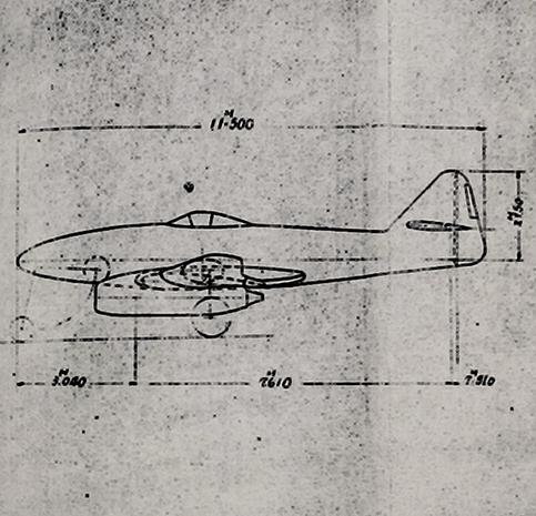
In the initial draft, Karyū had a conventional linear wing, with the airframe dimensions at a span of 12.56 m and a length of 10.55 m, a size nearly identical to the Me 262. Ultimately though, the airframe design settled on a shape that appeared closely to Me 262, with a larger footprint of 13.7 m span and 11.5 m length (a size exceeding Me 262, at 12.6 m span and 10.6 m length). Accordingly, the wings were swept, and the cross-section of the fuselage was distinctly triangular in the mid-section. A tricycle-type landing gear configuration was adopted. The engine selected was the Ne-230 turbine rocket, or alternatively the somewhat more powerful Ne-130, and one was suspended under each wing. Two 1,000 kg powder rockets installed under the fuselage would aid takeoff.
Around the time of late May or early June, the cockpit mockup examination of the Ki-201 was conducted. Iwao Shibuya took suggestions from pilots and other observation personnel, among them was Yoshio Nakamura, an engineer assigned to the development of the Ne-130 engine.
“Though I couldn’t even pilot an ordinary airplane properly, I settled into the cockpit of the Karyū, and dreamed of the appearance of the real Karyū, not made of plywood.”
-Yoshio Nakamura, member of the Army’s Ne-130 design team.
Karyū 6/1945 syllabus, highlighting the initial requirements and many specifications.
The basic design drawings of Ki-201 were finalized in June, almost perfectly to schedule. The basic shape of Karyū almost perfectly matches its parent, though it is considerably larger in dimensions. This was a sharp contrast to the Navy’s ‘Kikka’, also developed at Nakajima — due to Kikka’s low thrust engines, it had to be designed as a very small aircraft in order to be practical. On the other end, with the development of high-thrust turbojets as the engine for Karyū, the domestic production of a larger jet like the ‘Me 262’ was possible for the first time. However, it was around this time that troubles with the development of these very engines delayed the projected completion of Karyū No. 1 to March 1946, with the full-scale mock-up to be reviewed in August of the preceding year.
The detailed design of Karyū was begun in June, immediately after the basic stage was finalized. Though it bore an extremely similar resemblance to Me 262 externally, the detailed structure and materials were quite different due to the circumstances such as the lack of manufacturing plans and the severe material shortages at the time. Me 262’s construction had to be reverse-engineered manually using Japanese methods without any detailed design prints. One could say that the typical Japanese method of aircraft design was incorporated into the shape of the Me 262 to create the Karyū.
Me 262 A and Ki-201 to scale.
Nakajima’s original designs were applied in areas including the canopy, lateral shape, and vertical tail. The main aircraft material was the lightweight duralumin alloy SDH, and other materials such as silicon-manganese steel, carbon steel, and tin were used in various components on a smaller scale. Just like the Me 262, the airframe structure is semi-monocoque, and the wings were of single-spar (with an ‘auxiliary’ spar) construction, with slotted flaps and leading-edge slats splitting around the engines. Two main fuel tanks of 1,200 liters were located in front and behind the cockpit, with a 600 liter auxiliary tank set behind the rear tank, for a total fuel capacity of 3,000 liters. All fuel tanks were self-sealing, and the main tanks were equipped with automatic fire extinguishers. An 8 mm steel plate is provided in front of the cockpit, with 8 mm at the back and 12 mm at the head of the seat. The front of the windshield is composed of 70 mm of bulletproof glass.
Compared to Me 262 A, Karyū mounted engines of roughly the same power while increasing the size of the airframe. As such, the maximum top speed estimated by the designers was somewhat lower, though curiously it was projected to exceed Me 262 at extreme altitudes when utilizing Ne-130 engines. Karyū’s increased wing area granted it a lighter wing loading and a higher estimated climb rate.
Browning-derived Ho-155 Model II 30 mm Machine Cannon.
Me 262 A was well armed with a quartet of MK 108 autocannons in the nose for bomber interception, and Karyū, aiming to take down the B-29 bomber tormenting Japan, was similarly heavily equipped. The machine cannons on the lower outboard of the nose were 30 mm caliber, and the upper inboard two guns were 20 mm. For the Japanese Army, these guns were the Ho-155 Model II & Type2 respectively, powerful cannons loading fuseless shells able to down a heavy bomber in only a few hits. Both possessed a muzzle velocity roughly 200 m/s over that of the MK 108 and thus were more desirable for firing on air targets. Ki-201 would also be able to load a bomb as large as 800 kg, larger than the fighter-bomber Me 262 A-2a’s maximum bomb load of 500 kg, or a single 600l drop-tank for long-range missions. Radar ordnance consisted of a Ta-Ki Mk. 15 Friend-Foe Identification Radar, and a Ta-Ki Mk. 13 Low-Altitude Altimeter, both stored behind the cockpit along with the radio.
The detailed design work on the Karyū continued throughout July, and basic aerodynamics examinations were completed together with the wind tunnel testing of scale models at around the same time. Construction preparations of the first prototype also began this month, immediately before the end of the war. With just five months elapsed from the start of the design to this point, the startlingly frantic pace of Karyū’s development can be seen.
Ki-201 original design drawings. Note the annotation of Ne-130.
Unfortunately for Japan’s Me 262, it was on August 15th that the end of the war finally arrived. Although design work had progressed at a remarkably fast rate for the situation at the time, development was canceled here and the project ended wholly incomplete. If any actual manufacturing of components apart from the mockup preparation took place, it was not significant enough for the airframe to begin any considerable level of assembly. The IJA’s first and last jet fighter, Karyū, was never to grace the skies over Japan. This anticlimactic ending is a simple reality of most advanced wartime projects. It was a wasteful act for the Navy and Army to order Nakajima to develop a jet aircraft inspired by ‘Me 262’ at the same time, and Karyū’s development suffered as a result. In the end, had efforts been focused on one aircraft, more progress could have been made.
The status points taken from data submitted by Nakajima Aircraft at the war’s end follow:
About 50% completion of the design
About 0% completion of the prototype
Status
Started manufacturing full-scale mockup.
Only full-scale construction drawings complete.
The Ki-201 prototype was ‘0%’ completed at the end of the war.
The principle of Karyū was to create a high-performance jet aircraft sporting a devastating offensive armament capable of taking down the American Boeing B-29, as well as having the capability to equip a large bomb to attack the US fleet. Additionally, it was aiming to confront the Allied jet aircraft of a similar role developing at the time, such as the American Lockheed P-80 & British Gloster Meteor, noted by Nakajima. The prototype was to have been assembled near the Mitaka Institute, at a large hangar originally built for the canceled G10N “Fugaku” super-heavy bomber. The production of Karyū was scheduled to commence at the Nakajima Iwate factory, which was the dispersal factory of the Mitaka Institute.
The Mitaka Institute was remodeled into the International Christian University after the war, and the prototype Karyū’s assembly-site-to-be is now occupied by only a thicket of trees.
The head of examinations for the Ki-201 prototype was scheduled to have been Major Yoshitsugu Aramaki.
Ki-201 (estimated) Main Specifications:
(from June 1945 & August 1945 data sheets)
Dimensions
Full Width: 13.700 m Full Length: 11.500 m Full Height: 4.05 m Wing Area: 25.0 m2
Mounted Engine
Ne-230 (x2): 885 kgf each or Ne-130 (x2): 908 kgf each
Weights
Empty Weight: 4,465 kg Equip. Weight: 2,497 kg Normal Load: 6,962 kg Special Load: 8,469 kg
Top Speed Ne-230 (Ne-130)
726 km/h (740 km/h) @ SL 792 km/h (811 km/h) @ 6,000 m 812 km/h (852 km/h) @ 10,000 m
Wing Loading
278.48 kg/m2
Climb Rate Ne-230 (Ne-130)
18.9 m/s @ SL 726 km/h (740 km/h) @ SL 792 km/h (811 km/h) @ 6,000 m 812 km/h (852 km/h) @ 10,000 m
Crew
1 (pilot)
Cruising Range
100% Thrust: 794 km @ 8,000 m 80% Thrust: 888 km @ 8,000 m 60% Thrust: 980 km @ 8,000 m
Fuel Capacity
Normal Load: 2,120 l Special Load: 2,590 l
Practical Ceiling
13,600 m
Oil Capacity
Normal Load: 80 l Special Load: 100 l
Never Exceed
1,000 km/h
Armament
Ho-155II 30 mm (120 x2) Type 2 20 mm (200 x2) or Type 2 20 mm (200 x4)
Takeoff
Normal Load: 200 km/h / 949 m Special Load: 210km/h / 1,580 m
Ordnance
No. 50 Bomb (500 kg) x1 or No. 80 Bomb (800 kg) x1
Radar
Ta-Ki 15 IFF Ta-Ki 13 Low Altimeter
Mitaka prototype factory hangar (centre-back) where the prototype Karyū would have been assembled.
High-Power Engine Development for ‘Karyū’
Both of the engines scheduled for Karyū, Ishikawajima Shibaura Turbine’s Ne-130 and 1st Munition Arsenal (formerly Nakajima Airplane)–Hitachi Manufacturing’s Ne-230, were at approximately the same stage of development when the war ended. Neither was ready for use. The larger and heavier Mitsubishi Ne-330, as previously mentioned, wasn’t considered for the final Ki-201. It is quite remarkable that the Japanese were able to engineer these turbojets, most famously the smaller Ne-20 for Kikka, with little more than a cutaway of a BMW 003 and even less material availability than Germany.
The first unit of Ne-130 was completed at the end of May 1945, and the team at Tachikawa tested it as far as 8,000 RPM when the engine heavily damaged itself. The cause was hairline fractures in the construction of the compressor blades, which caused the blades to splinter off during high-stress operations. The second engine was completed in early July and eventually successfully tested at full power in August. However, when testing again with accurate measuring equipment on August 16th, one day after the war’s end, the compressor blades were damaged by a foreign object being inhaled. Unit three was completed but had been destroyed on August 2nd when the Tsurumi factory was bombed. As such, there ultimately were no functional Ne-130 engines in the possession of the Japanese.
*Info about Ne-230 is scarce, and this section is not accurate to date. The first Ne-230 was completed at Mitaka in March 1945. Unit two was finished in May, with the final unit in June. During the testing at Takahagi, while applying countermeasures for faults in the engine’s testing, it is said that the engines (a number or all) were damaged by a bombing raid. No engine was transferred to the US for testing after the war, and as such it’s fairly likely that no functional engine survived the war. In late 2017 the parts of two Ne-230 engines were found in the International Christian University, which was formerly known as the Mitaka Institute. The remains included two nozzles and a cover. There is a possibility that these were not ever part of a functional engine, as they show no obvious signs of being bolted to other pieces. Of the late engines, only Ne-230’s drawing is not present.
In the end, the only successful Japanese turbojet to reach mass production was the Ne-20. This engine was developed for the Navy’s Kikka, and was smaller and less powerful than the engines for the Army’s Karyū, providing only about 490 kgf of thrust. Development progressed quickly as a result, and Kikka flew for the first time in August 1945, the first and last Japanese turbojet aircraft to do so in World War II. From Kikka to Karyū, it could be said that the great driving force of the jet development program in Japan was always the inspiration of the “Me 262”.
“Kikka” which, unlike Karyū, made it to the stage of test flight. Though a rough resemblance could be observed, this Nakajima aircraft was not a copy of the Me 262, nor related to the Ki-201.