
Unclassified (FU)
9 April 1942
Naval Air Technical Depot Unclassified (FU) #02-40
Report on Results of Research Experiments
Air Technical Report 02135
FREE PISTON TWO-STAGE-COMBUSTION INTERNAL
COMBUSTION TURBINE AND TURBINE ROCKET
(Research on Internal Combustion Rockets – 6th Report)
Naval Air Technical Depot
Unclassified (FU)
Report Number: 02135
Engine Report 0228
Research Experiment Station: Engine Department, Naval Air Technical Depot
Period of Research Experiment: From April 1942 to March 1942
Research Experiment Number: 1942 Engine Experiment #21
Person in Charge of Research Experiment: Commander Tanegashima Tokiyasu
Classification of Instruction, Notification, etc.: Naval Air HQ Secret #3500 Notification of 31 March 1942.
Report Prepared by: Commander Tanegashima Tokiyasu
Purpose: To discuss theoretically the use of the Free Pistol Two-Stage-Combustion Internal Combustion Turbine and Turbine Rocket as power units for aircraft.
Summary of Results:
- It is anticipated that the Free Piston Two-Stage Internal Combustion Turbine can be used as a power unit for aircraft. Moreover, compared to general constant pressure combustion cycle turbines such as the Brown Boveri type, there is a possibility of developing a turbine which is far superior in output and thermal efficiency. To summarize the superiority over the general type, output is raised about 5 to 6 times and thermal efficiency about 2 times. According to calculations in the text, the thermal efficiency is about 30%. Moreover, gasoline is not required as a fuel. Aviation diesel oil is suitable for the free piston, and an even lower grade of heavy oil for the two-stage combustion chamber.
- Turbine Rockets have great promise as a suitable propelling power unit for very high speed planes (900 km/h and above). Moreover, it appears that it will be difficult to attain such high speed with ordinary propeller type propulsion. It may be estimated that at these high speeds the thrust efficiency of this rocket is about 14% (with a propeller and ordinary engine it is below 10%).
Opinion of OinC, Naval Air Technical Depot: Considered good reference for data for internal combustion turbines and turbine rockets.
Opinion of Naval Air HQ: (None)
1. Purpose
To discuss theoretically the use of the free piston two-stage-combustion internal combustion turbine and turbine rocket as power units for aircraft.
2. Results and Opinions
- Results:
In a theoretical investigation of cases in which free piston two-stage-combustion internal combustion turbines and turbine rockets are used in aircraft, the following results were obtained:- Definition of Methods:
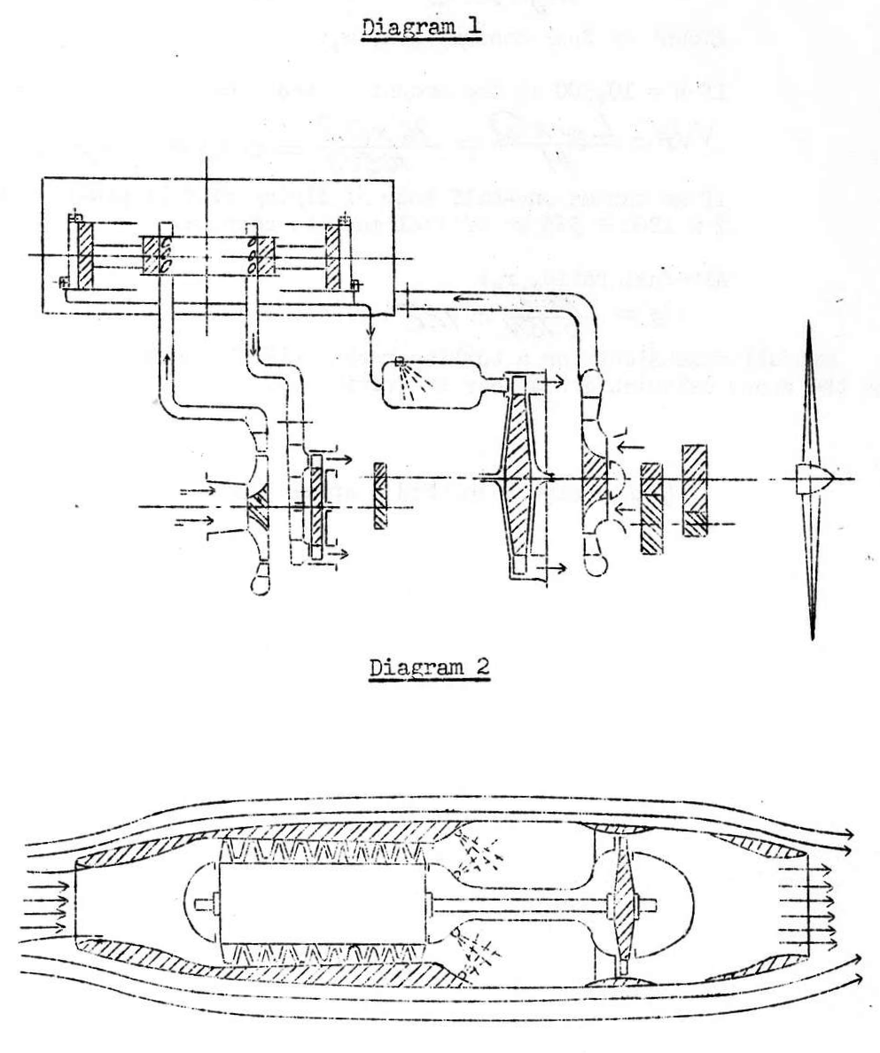
- Free piston two-stage-combustion internal combustion turbine method:
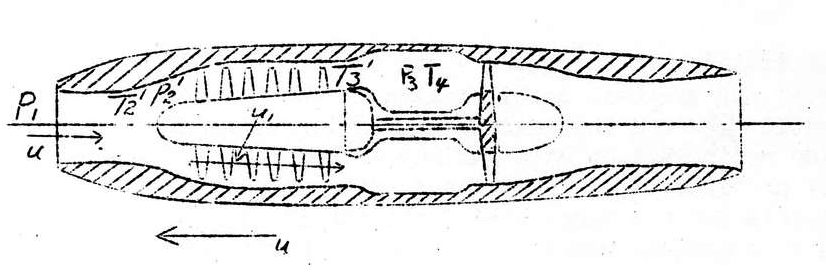
The turbine is driven by leading compressed air discharged by a free piston type internal combustion air pump into a combustion chamber and expelling it from a jet after constant pressure combustion has occurred (Drawing #1). - Turbine Rocket method:
The intake air is compressed by combining the effect of both the dynamic pressure produced by the forward movement of the plane and the compressor, and is expelled from jets after constant pressure combustion has occurred in the combustion chamber. The compressor is driven by the turbine, and by using the residual velocity which comes from the turbine vanes for a rocket effect, the plane is propelled forward.
- Free piston two-stage-combustion internal combustion turbine method:
- Theoretical Considerations:
In the method cited in Section 1 above, the thermal efficiency of the turbine shaft horsepower is extremely high, and it may be possible to attain almost 30%.
Moreover, compared to types which do not use the two-stage-combustion heretofore announced, it is expected that power output will increase 1.5 to 2.0 times. This model/type possesses the best qualities among the various types of internal combustion turbines.
It may also be possible to get good results from the method cited in Section 2 above, according to theory. This type is the most suitable for ultra-high speed planes. The entire thermal efficiency, including thrust thermal efficiency, is about 14.5% at a speed of 1000 km/h. It has been made clear that this is a value which cannot be achieved at ultra-high speeds with the propeller type propulsion.
*Air Technical Report 0120 (18 Jan 1941)
- Definition of Methods:
- Opinions
It is thought that the development of ultra-high horsepower aircraft power units is already a matter of the immediate future, but along with increasing the horsepower of reciprocating type engines, it is characteristically necessary to increase the number of cylinders as well. In contrast to this, the fact that turbines can easily achieve great horsepower is clearly seen in examples of high horsepower turbines used in ships and on land. It appears at first glance that those turbines which employ a free piston as explained in the first method are unwieldy because they have a reciprocating part, but since the free piston, by its very nature, is able to eliminate almost all the defects of an ordinary reciprocating engine, there is not the slightest disadvantage in its use. Moreover, it is characteristic of the operating cycle of this type that thermal efficiency is very high and output is also extremely great. It is expected that it will prove superior to the present aircraft engine in these respects. Moreover, since the free piston operates through a diesel cycle and the injection of any type of fuel in the combustion chamber makes no difference, it is not necessary to use high grade gasoline. There are other advantages as well. Therefore, an internal combustion turbine based on this method is considered capable of being a highly superior power unit.
The second method has characteristics which make it a very superior propelling apparatus for high speed planes. From the standpoint of construction, by this method it is suitable to use an even lower grade fuel; and this method is therefore considered an especially suitable propulsion method for ultra-high speed planes.
3. Text
- Scientific Analysis of the Thermo-Dynamics of the Free Piston Two-Stage-Combustion Internal Combustion Turbine
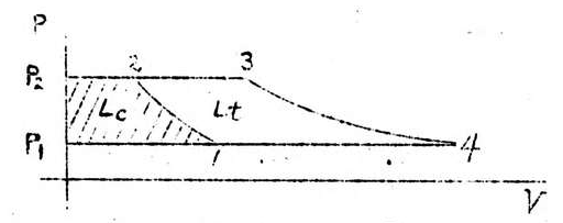
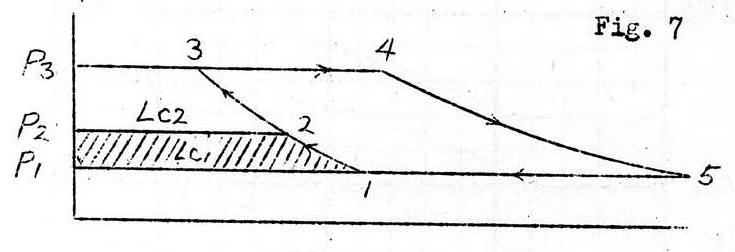
Area\space1\cdot P_1\cdot P_2\cdot2(L_c) . . . . Work of compression
Area\space4\cdot P_1\cdot P_2\cdot3(L_t) . . . . Kinetic energy which can be utilized by the turbine.
The effective work transmitted to the shaft in the cycle of previous combustion turbines is L_o=L_t n_t-\frac{L_c}{n_c}
Moreover, n_t and n_c are the respective total efficiencies of the turbine and of the compressor, but in this cycle, L_o=L_t n_t.
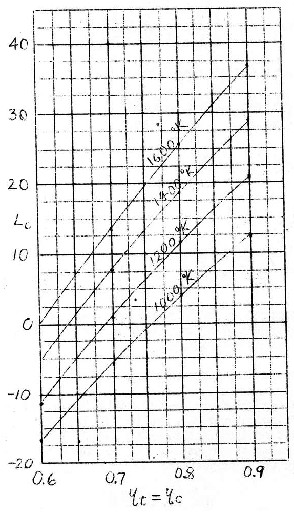
In actual circumstances, \frac{L_c}{n_c} has a fairly large numerical value. Actual examples appear in the following table. This table is calculated from Stodola’s gas entropy graph.
| T_3=1000°K\space P_1=1\space P_2=10 | |||||
| nt=nc | Lt | Lc | Lf | L_o=L_t n_t-\frac{L_c}{n_c} | n_{th}=\frac{L_o}{L_f} |
| 60% | 47 | 27 | 37.8 | -16.8=47×0.6-27/0.6 | -44.5% |
| 70% | 47 | 27 | 37.8 | -5.6=47×0.7-27/0.6 | -14.8% |
| 80% | 47 | 27 | 37.8 | 3.8=47×0.8-27/0.8 | -10% |
| 90% | 47 | 27 | 37.8 | 12.3=47×0.9-27/0.9 | 12.3% |
| T_3=1200°K | |||||
| 60% | 56.3 | 27 | 57.5 | -11.2=56.3×0.6-27/0.6 | -19.3% |
| 70% | 56.3 | 27 | 57.5 | 0.9=56.3×0.7-27/0.7 | 1.57% |
| 80% | 56.3 | 27 | 57.5 | 11.2=56.3×0.8-27/0.8 | 19.3% |
| 90% | 56.3 | 27 | 57.5 | 20.8=56.3×0.9-27/0.9 | 36.2% |
| T_3=1400°K | |||||
| 60% | 65.4 | 27 | 75.3 | -5.8=65.4×0.6=27/0.6 | -7.7% |
| 70% | 65.4 | 27 | 75.3 | 7.2=65.4×0.7=27/0.7 | 9.54% |
| 80% | 65.4 | 27 | 75.3 | 18.5=65.4×0.8=27/0.8 | 24.5% |
| 90% | 65.4 | 27 | 75.3 | 28.8=65.4×0.9=27/0.9 | 38.2% |
| T_3=1600°K | |||||
| 60% | 74 | 27 | 92 | -0.5=74×0.6=27/0.6 | -0.545% |
| * 70% | 74 | 27 | 92 | 13.2=74×0.7=27/0.7 | 14.35% |
| 80% | 74 | 27 | 92 | 25.4=74×0.8=27/0.8 | 27.6% |
| 90% | 74 | 27 | 92 | 36.6=74×0.9=27/0.9 | 39.8% |
Notes
L_f. . . .Energy given by fuel
n_{th}. . . .Thermal efficiency
The values of L_t\space L_o\space L_f are shown by areas (cm2) on the entropy graph.
This table may be expressed by means of curves as follows:
To explain an example taken from the * entry of the above table:
L_c=L_t y_t-\frac{L_c}{y_c}=45.8-38.6=7.2
y_{th}=\frac{L_o}{L_f}=\frac{7.2}{75.5}=9.54\%
When \frac{L_c}{n_c} is assigned to the free piston, L_o equals 45.8, which is 6.36 times the power output of the former. Moreover, the thermal efficiency for the case in which the free piston is used may be calculated by the following method:
K=\frac{L_t y_t}{L_c}=\frac{65.4\cdot0.7}{27}=1.7
Assuming that for L_c, n_{th1}=0.35
For L_t n_t, n_{tk2}=\frac{L_t n_t}{L_f}=65.4\cdot \frac{0.7}{75.3}=0.605
The total amount of fuel consumption is:
F_c=\frac{L_c}{y_{th1}}+L_f=\frac{L_c}{y_{th1}}+\frac{L_t y_t}{y_{th2}}
=L_c(\frac{1}{y_{th1}}+\frac{K}{y_{th2}})
=5.68L_c
That is, an internal combustion turbine may be obtained which is far superior in both output and thermal efficiency to the ordinary combustion cycle such as the Brown Boveri type.
Selection of operating pressure combustion temperature:
When the operating pressure is too high, the construction of the free piston becomes difficult; and when it is too low, the piston becomes too large and the effect of turbinization is lost. Therefore, there are naturally proper limits to pressure. It is convenient to use the following curves to study this subject:
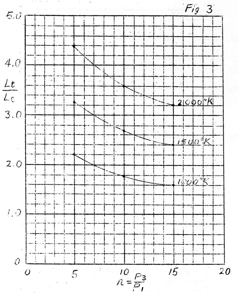
Fig. 3 depicts \frac{L_t}{L_c} with the combustion temperature as a parameter for compression ratio r.
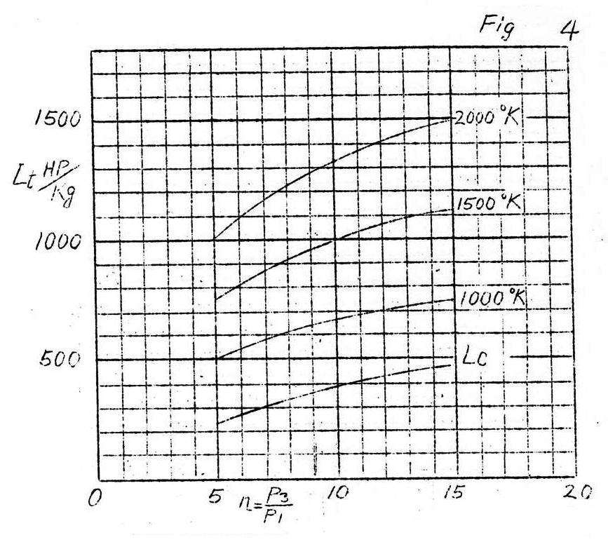
The curves in Fig. 4 indicate the L_t generated for the gas in 1 kg/sec of combustion in terms of horsepower.
The curves in Fig. 5 show the relationship of the compression ratio to the temperature of the gas expelled from the jet.
Fig. 6 shows the relationship of the compression ratio to the theoretical jet velocity.
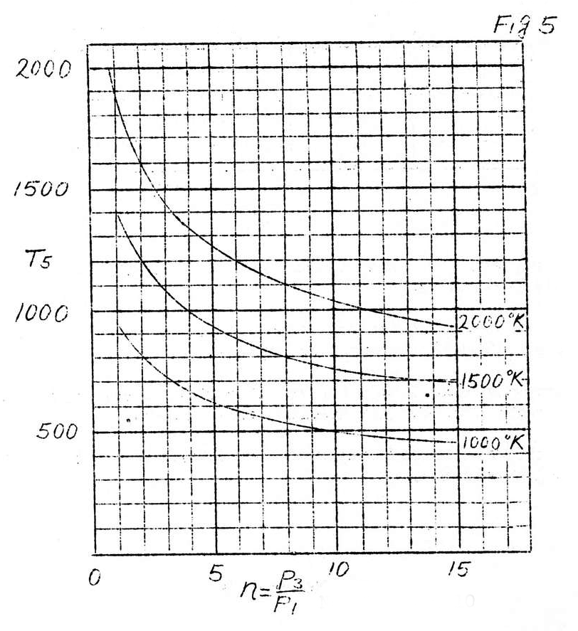
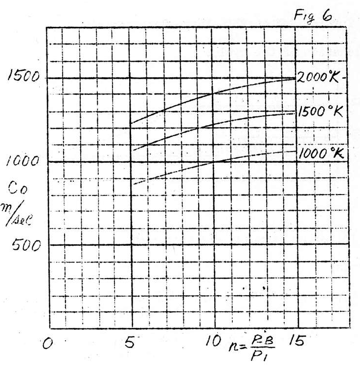
From these curves, if we take
Compression ratio, r, as 10
Combustion temperature as 1500°K
then \frac{L_t}{L_c}=2.7
T_5=700°K
C_o=1,220m/sec
It is believed that in view of the design of the internal combustion turbine, fairly reasonable numerical values have been obtained for the strength and rpm of the vanes and for factors such as size.
- The Turbine Rocket
Explanation of the cycle:
The following formulas are obtained:
Symbols:
L_{c1}\space (Area\space 1\cdot P_1\cdot P_2\cdot 2) Work of adiabatic compression due to forward motion air flow.
L_{c2}\space (Area\space 2\cdot P_2\cdot P_3\cdot 3) Work of adiabatic compression due to compressor.
L_t\space (Area\space 5\cdot P_1\cdot P_3\cdot 4) Total kinetic energy which can be used by turbine.
n_{c2} Blower efficiency.
n_t Turbine efficiency.
C_r Rocket discharge velocity.
F Airframe resistance
u Plane speed; u_1 velocity of flow within air blower
m Amount of airflow per second.
n_{c1} Pressure efficiency of collector.
L_{t1} Kinetic energy of turbine used for driving the blower.
n_{t1} Turbine efficiency of above (this efficiency does not include residual velocity loss.)
L_r Residual kinetic energy used for rocket.
n_r Efficiency at rocket discharge opening.
L_q Amount of heat added.
\frac{L_{c2}}{y_{c2}}=L_{t1}\cdot y_{t1} —— (1)
C_r=\sqrt{29(L_t-L_{t1}y_r}
C_r=\sqrt{29L_ry_r} —— (2)
F\cdot u=mC_ru-\frac{mgL_{c1}}{y_{c1}}-\frac{1}{2}mu^2 —— (3)
\hspace{65px}(Comp)\hspace{5px}(Acc)
That is, the first item is the work of the reaction force. The second is the work required to compress the air from 1 to 2. The third is the work necessary to cause the air to accelerate to the same velocity as the plane.
However, in L_{c1}=\frac{1}{2g}(u^2-u_1^2, when u_1 is smaller than u,
L_{c1}=\frac{1}{29}u^2
F_u=mC_ru-(\frac{yc_1+1}{yc_1})\frac{1}{2}mu^2 —— (4)
When n_{c1} is 1.0 (or above 0.9, which is almost the same)
F_u=mv(Cr-u) —— (5)*
*Formula (5) was published in a previous report (Air Technical Report 01361)
as F_u=muC_r-\frac{1}{2}mu^2 —— (A)
As a result of later research, discrepancies were discovered in the calculation of the outflow velocity, C_r, in the previous experiment. Therefore, although the above formula was thought to have been established in the previous experiment, from later research this formula was judged to be the same as formula (4) as given here, and was conjectured to be one from which (5) could be derived. Consequently, formula (A) of the previous report has been revised to formula (5).
Further,
L_{c1}=\frac{u^2}{29}-\frac{u_1^2}{29}=\frac{n}{n-1}RT_1[(\frac{P_2}{P_1})^{\frac{n-1}{n}}-1] —— (5)1
=\frac{n}{n-1}RT_2[\frac{T_2}{T_1}-1]
=J.C.P(T_2-T_1) —— (6)
R=J(C_p-C_r)
From the relation, n=\frac{C_p}{C_r}
\frac{n}{n-1}R=J.C_p
In the same manner,
L_{c2}=\frac{n}{n-1}RT_2[(\frac{P_3}{P_2})^{\frac{n-1}{n}}-1]=J.C_p(T_3-T_2) —— (7)
L_t=\frac{n}{n-1}RT_4[1-\frac{1}{(\frac{P_3}{P_2})^{\frac{n-1}{n}}}]=J.C_p(T_4-T_5) —— (8)
and L_q=J.Cp(T_4-T_3)
In addition to designing a gas turbine of this type, the problem requiring the greatest consideration is the selection of the compression ratio \frac{P_2}{P_3} and the maximum combustion temperature T_4. The compression ratio must be at a maximum within limits which permit the highest possible efficiency of the rotary compressor; and a temperature T_4 suitable for the vanes behind the turbine jet outlets must be selected at a maximum within the limits of safety for the material of the vanes.
The following is an example of the calculation of the actual numerical values:
Sample calculation:
In one actual fighter plane, u = 700 km/h, B.H.P. = 1100.
If we let n_p=70%, resistance F=297kg.
In order for this fighter plane to attain 1000 km/h, if we assume that resistance is proportional to u^2 up to this velocity, F=714kg.
The required horsepower at this velocity, if n_p=50%, is B.H.P.=5300 H.P.
Weight of engine: 0.6 x 5300 = 3180 kg.
Weight of propeller: 0.2 x 5300 = 10.60 kg. (* obtained from Aircraft Dept.)
Total: 4240 kg.
Thermal efficiency:
y_{th}=\frac{60.25}{m}=\frac{60.25}{320}=18.7%
However, m is the fuel consumption ratio, g/h.p/n
y_{th.p}=18.7*0.5=9.36%
That is, it would be totally impossible for this type of fighter, equipped with a propeller providing a force of 4.24 tons, to attain a velocity of 1000 km/h.
Turbine Rocket
Airplane velocity u=1000 km/h=278 m/s
Blower compression ratio P3/p2=3
Intake air weight Q=18.8 kg/sec
Air temperature 15°C
Air pressure P_1=1 kg/cm^2
Air velocity at inlet u=278 m/sec
Axial flow velocity within blower u_1=80 m/sec
Kinetic compression P_3^1
From formula (5),
(\frac{P_2}{P_1})^{\frac{n-1}{n}}=1+\frac{n-1}{n}\cdot\frac{r_1}{P_1}[\frac{u^2}{29}-\frac{u_1^2}{29}]
P_2=1.52 kg/cm^2 is obtained.
Assuming a pressure efficiency of the collector of 90%,
P_2^1=1.468 kg/cm^2.
Rise in dynamic pressure temperature T_2:
T_2-T_1=\frac{1}{JCp}(\frac{u^2}{29}-\frac{u_1^2}{29})
n=1.4
J=427 Kg.M
Cp=0.24 kcal/kg
T_2=288+35.1=323.1\degree K
Note: Because of the effect of the collector efficiency, the pressure which is thought of as adiabatic compression is lower than the /actual/ adiabatic compression pressure, but since the friction is converted to heat, the temperature is proportional to the adiabatic compression.
Work of the blower \frac{L_{c2}}{J}
Compression ratio \frac{P_3}{P_2^1}=3P_2^1=1.468
Temperature T_3
T_3=T_2(\frac{P_3}{P_2^1})^{\frac{n-1}{n}}=433\degree K
T_3-T_2=109.9\degree C
T_3^1-T_2=\frac{T_3-T_2}{y_{ad}}=141\degree C
But assume y_{ad}=y_{c2}=0.85
T_3^1-464.1\degree K=176.1\degree C
W=\frac{L_{c2}}{Jy_{c2}}=C_p(T_3^1-T_2)=0.24*141=33.8Kcal
Total HP = \frac{W.J.Q.}{75}=3620HP
Maximum combustion temperature T_4:
T_4=823\degree K(550\degree) . . . . . Given
Added combustion q:
L_q=C_p(T_4-T_3)=86kcal/kg is the kinetic energy used by the turbine L_t.
Temperature after adiabatic expansion, T_5:
T_5=\frac{T_4}{(\frac{P_3}{P_4})^{\frac{n-1}{n}}}=540\degree K
P_4=1.0
\frac{1}{J}\cdot L_t=C_p(T_4-T_5)=68kcal/kg
Turbine output necessary to drive the blower:
\frac{L_{c2}}{y_{c2}}=L_{t1}\cdot y_{t1}, \frac{L_{t1}}{J}=\frac{L_{c2}}{Jy_{c2}}\cdot \frac{1}{y_{t1}}=42.3kcal/kg
y_{t1}=0.8
(Note: because there is only friction eddy loss which includes no residual loss, this degree of efficiency is easily obtained)
Residual kinetic energy which can be used by rocket, L_r
\frac{1}{J}L_r=\frac{1}{J}(L_t-L_{t1})=25.7kcal/kg
Rocket ejection velocity, C_r
C_r=\sqrt{2qL_ry_r}=464m/sec . . . From formula (2)
Note: Since frictional losses at the discharge jet can be insignificant as the jet diameter is large, this is abbreviated, and n=1.0
Reaction force:
From formula (5), F=\frac{Q}{g}\cdot (C_r-u)=357 kg
Rocket horsepower: H\cdot P_p=\frac{F\cdot u}{75}=1330 H\cdot P
Using two of these turbine rockets
Propelling horsepower 2660 HP
Total thrust 714 kg
Wt of turbine rocket 700 kg\cdot 2*
*Weight calculated from overall plan.
Thermal efficiency:
y_{tn}=\frac{HP_p\cdot 75}{L_g\cdot J\cdot Q}=14.5%
Amount of fuel consumption, w_f:
If H=10500 is the amount of heat generated by the fuel,
W_f=\frac{L_g\cdot Q}{H}=\frac{86\cdot 18.8}{10500}=0.154 kg/sec
If we assume one-half hour of flying at full power, 0.154\cdot 2\cdot 1800=555 kg of fuel must be carried.
Air-fuel ratio, r_a:
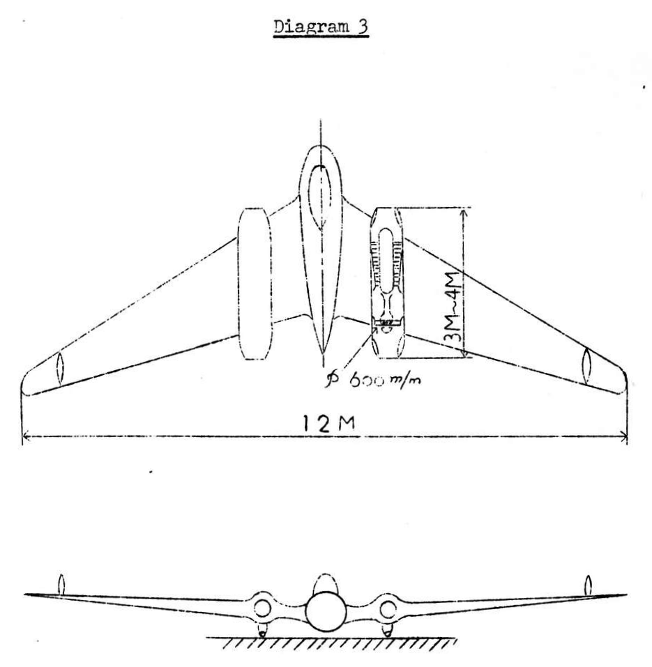
r_a=\frac{18.8}{0.154}=122
Overall dimensions for a turbine rocket based on the above calculations appear in Drawing #3.
(Manuscript completed 9 April 1942)
Leave a Reply