PM-18
November 1945.
NAVY DEPARTMENT
BUREAU OF AERONAUTICS
WASHINGTON
POWER PLANT MEMORANDUM NO. 18
JAPANESE POWER PLANTS FOR JET PROPULSION
Prepared by: R. M. SALTER, JR,
Lieutenant, USNR.
Approved by: S. B. SPANGLER,
Captain, USN.
A. Introduction. –
1. The purpose of this report is to present preliminary data on Japanese jet engines in general and Japanese turbo-jets in particular.
Information received to date reveals a rather meager embarkation by the Japanese into the field of jet propulsion. Apparently the Air Ministry was reluctant to allocate any of the reciprocating power plant facilities for a jet program, relying instead on Navy Yards and the Air Technical Arsenal. The Navy Yards, needless to say, were unfamiliar with problems involved in building aircraft power plants and in working with light metals. Three Ne 20 turbo-jet units produced at the Yokosuka Navy Yard were tested at Hadano by the jet engine laboratory of the Air Technical Arsenal and found to be poor in quality.
Although the Japanese had a few original turbo-jet designs these were cancelled in favor of four engines based upon the German BMW 003.
German designs also were used in the Japanese liquid fuel rocket engine. The KR-10 is apparently a Japanese built Walther R-211 unit.
Other types of jet power plants tried were an intermittent jet engine and a Campini type engine.
B. History. –
1. Turbo-jets. Japanese jet development began in 1942. Initial work was done by the First Air Technical Arsenal and employed centrifugal compressors. The first of these was undesignated but served as a prototype for the TR-10. The TR-10 produced 770 lbs. thrust and was to be used in the twin-engined “anti-invasion” bomber Kikka. The TR-12 was the next of the series and represented an improved TR-10 with four axial compressor stages added; thus following a compressor development pattern similar to the German Heinkel-Hirth engines. The TR-12 was considered to be too heavy. The TR-12B followed with a weight of 770 lbs. This latter engine was abandoned in March 1945 in favor of the Ne 20. It was found that the TR-12B lagged considerably behind the development of the Kikka airframe. About 40 of these engines were fabricated. (Figure 15).
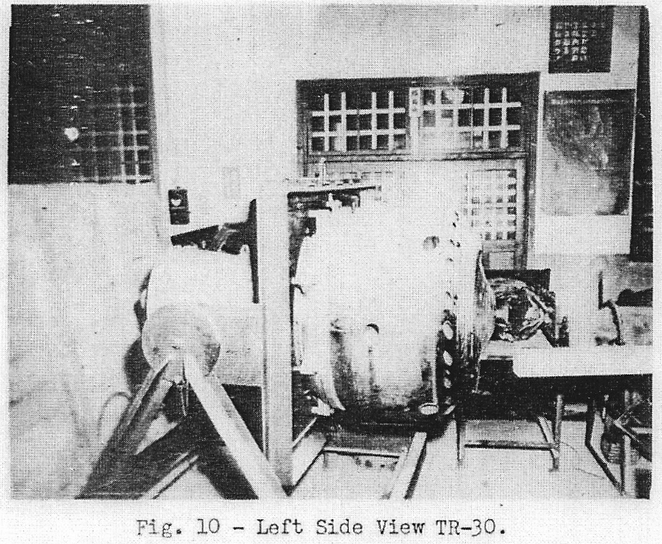
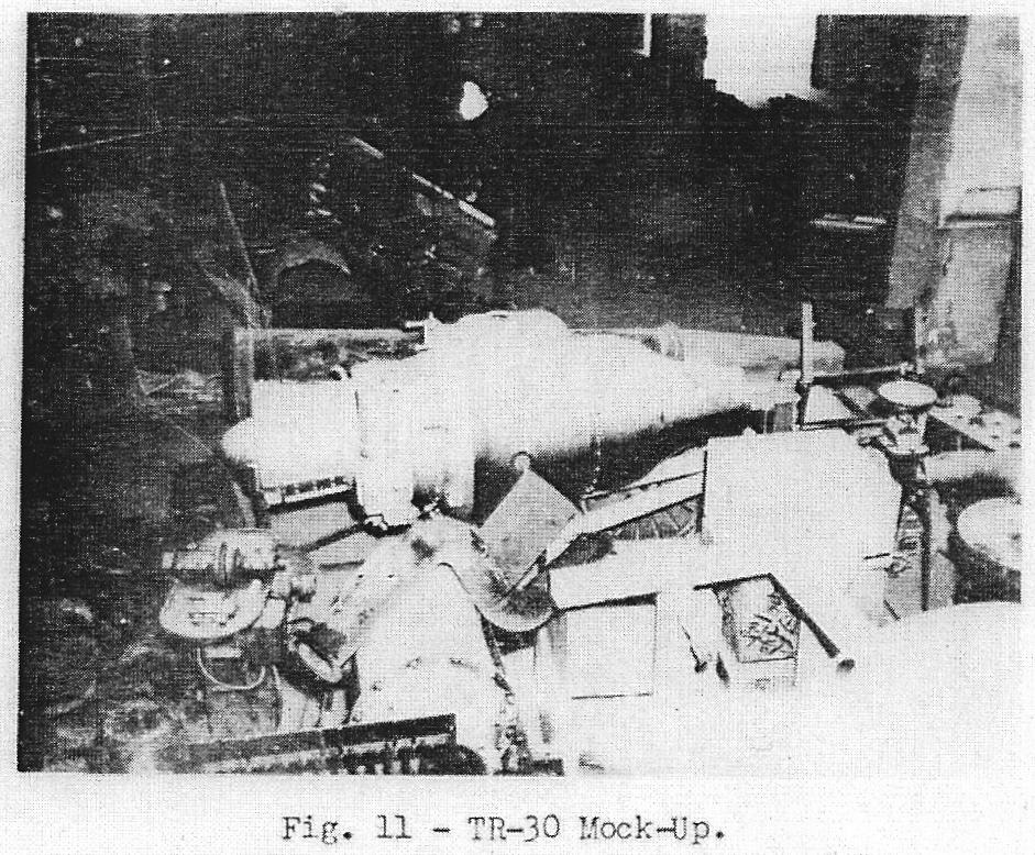
The TR-30 was an enlarged TR-12B and two TR-30’s were to be installed in Keiun, a reconnaissance plane. The TR-30 was also abandoned in favor of the Ne 20 in December 1944. (Figures 10 and 11).
In May 1944 photographs of the BMW 003 arrived by submarine. A companion sub containing production drawings was sunk enroute. From the 003 photo prints evolved four engines, the Ne 20 by the Air Technical Arsenal, the Ne-130 by Ishikawajima, the Ne 230 by Hitachi and the Ne 330 by Mitsubishi.
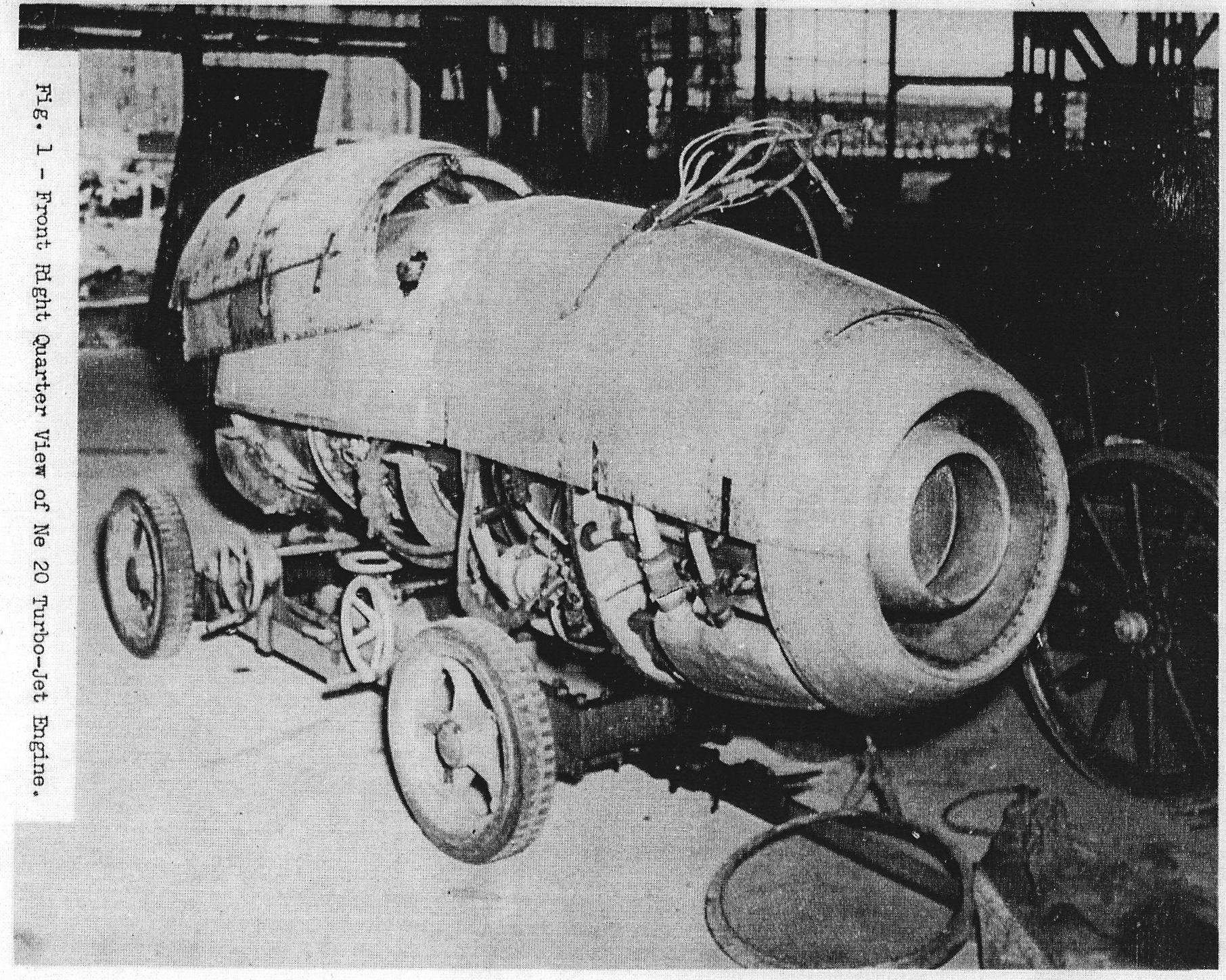
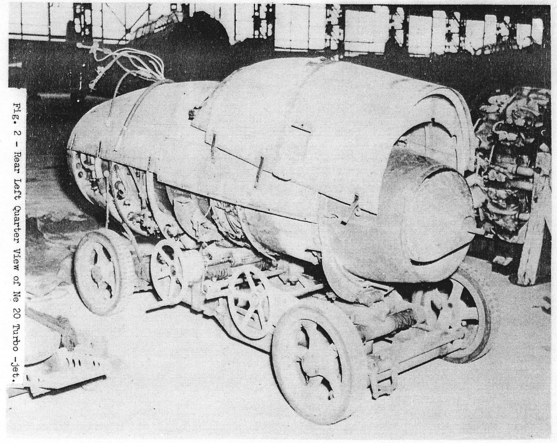
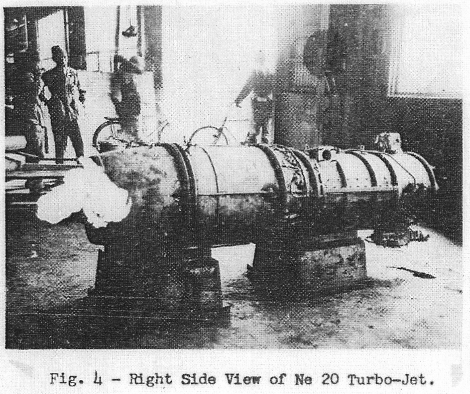
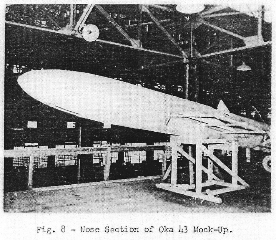
The Ne 20 is about a three-quarter sized 003 and was ready for production in the summer of 1945. (Figures 1-7). It was flight tested successfully in Kikka in August 1945. The Ne 20 was also destined for the Oka 43 (Baka). (Figures 8 and 9). Nine engines were built by the Air Technical Arsenal and 12 by the Yokosuka Navy Yard. This latter agency was to be the manufacturer of the Ne 20. To date only two Ne 20’s have been recovered.
Of the three reciprocating engine manufacturers experimenting in turbo-jets, Ishikawajima probably was in a better position than Hitachi or Mitsubishi due to the latters’ production commitments for conventional engines. In addition to the Ne-130, Ishikawajima also designed the Ne 140 and the GTPR. The Ne 140 was a larger engine than the Ne 130 and served as a prototype for it. The Ne 130 was compares more closely in performance to the BMW 003 than any other Japanese turbo-jet. The Army was interested in Ne 130 for use in Koryu. The GTPR (Gas Turbine Propeller Rocket) was an ambitious propeller gas turbine design originally involving a 19 stage axial flow compressor, four combustion chambers and a three stage turbine. (Figures 12-14). A later GTPR design was promulgated with a 12-stage axial compressor with a 4:1 pressure ration, 5-stage turbine and an annular combustion chamber of the BMW type employing 12 burners. The engine rpm was to be 5000 and the propeller rpm 1500. The prop reduction was to be of the double helical spur type. The length was estimated to be 18 ft, diameter 31.5 inches and weight 5500 lbs. Estimated sea level power was 3500 bhp delivered to the propeller and 1500 equivalent jet thrust bhp at 373 mph. Operating temperatures were expected to be 1290°F. combustion chamber and 840°F. tail pipe. The GTPR was destined for a large low speed, low altitude airplane. Research on the GTPR was terminated in August 1944 probably since it was a rather long range project, although some component testing was done.
The Ne 130, Ne 230 and Ne 330 were in approximately the same state of development at the war’s end. One model of the Ne 130 was produced but was destroyed on bench test. The Ne 230 was also completed and was under test by the Navy at Takahagi. The Ne 330 was almost completed but work was terminated due to air raid damage. The best of the three above engines was to be used in Keiun.
2. Campini-type engines. Early Japanese jet propulsion efforts were directed along the lines of the Campini system. Documents recovered in 1942 show that this type of engine was being investigated at that time.
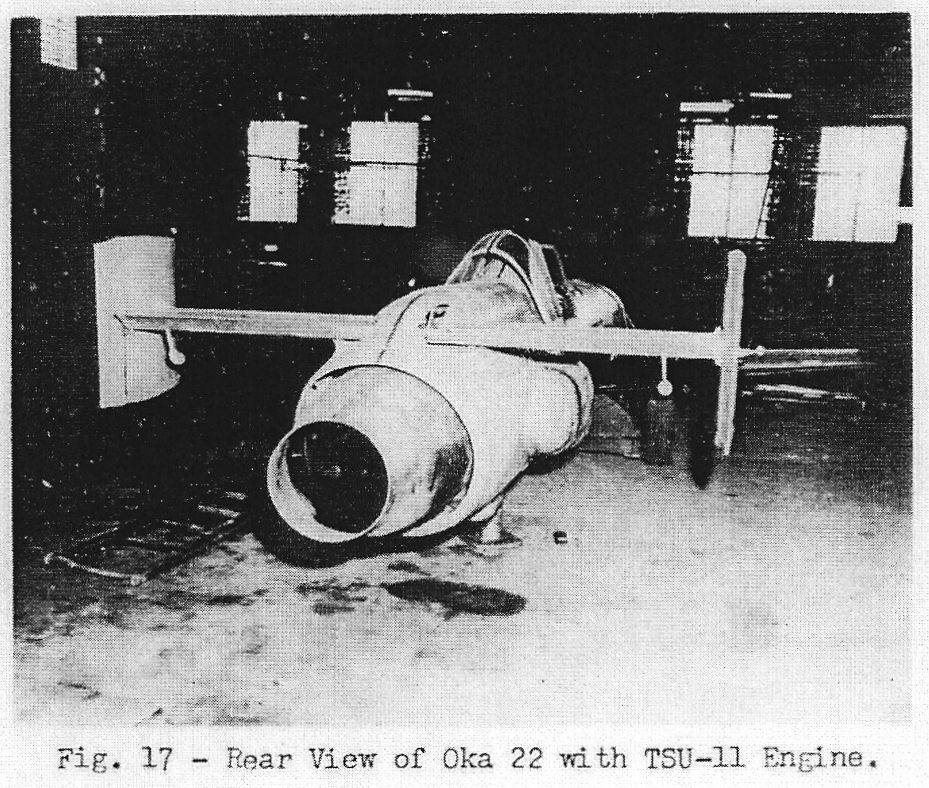
As a stop gap between the Oka 11 (Baka with solid propellant rockets) and the Oka 43 for the Ne 20, the Oka 22 with the TSU-11 Campini-type engine was developed by the Air Technical Arsenal. (Figures 16 and 17). The TSU-11 is a Hatsukaze 11 four-cylinder inverted in-line air-cooled engine driving a single stage axial compressor. The Hatsukaze is rated at 150 bhp at 3000 rpm. The compressor is geared up 3:1 and rotates at 9000 rpm. The compressor wheel is 21.3 inches in diameter with an effective blade height of 3.8 inches. Four fuel burners are located aft of the compressor to provide afterburning. Three TSU-11 engines were built. Flight tests were made in 1944 using the TSU-11 as a booster for Frances. One successful flight of an Oka 22 was made in July 1945, the Oka 22 being launched from a Frances.
Hitachi began manufacturing of the the TSU-11 in June 1945 and was also experimenting with a similar type of power plant. This latter was designated the M.T.P.R. and consisted of a combination propeller – reciprocating Atsuta engine and turbo-jet. Part of the reciprocating engine power was transmitted to the compressor of the turbo-jet. This project was abandoned in August 1944 in favor of the Ne 230.
3. Miscellaneous engines. The Air Technical Arsenal tried various other type of jet engines. These were the KR-10 (TOKU-RO2) bi-fuel rocket, the Ka 10 intermittent-jet, and a Pescara type free piston compressor design study.
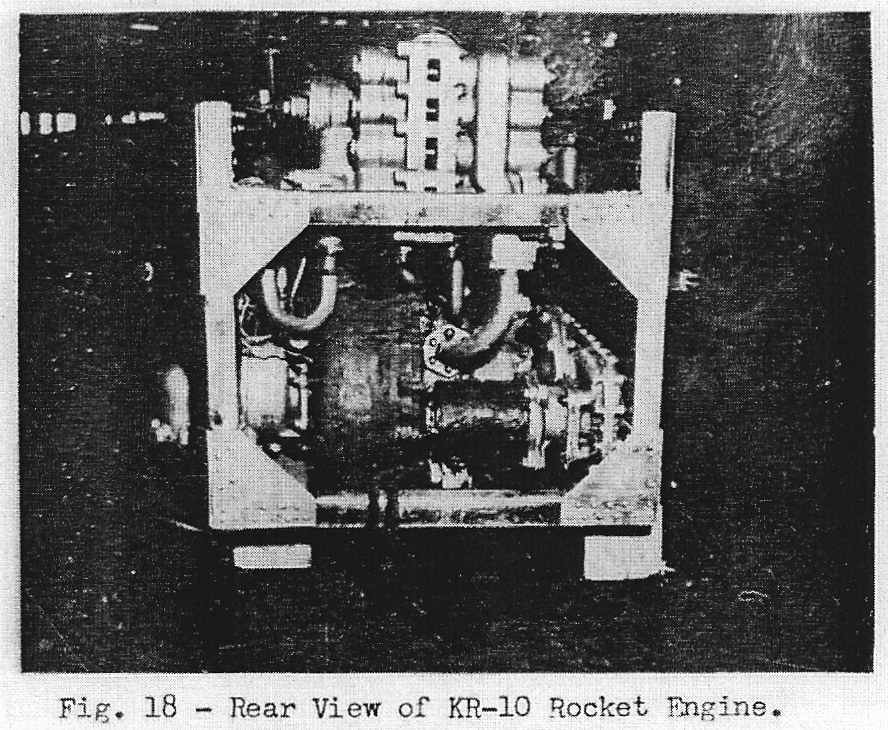
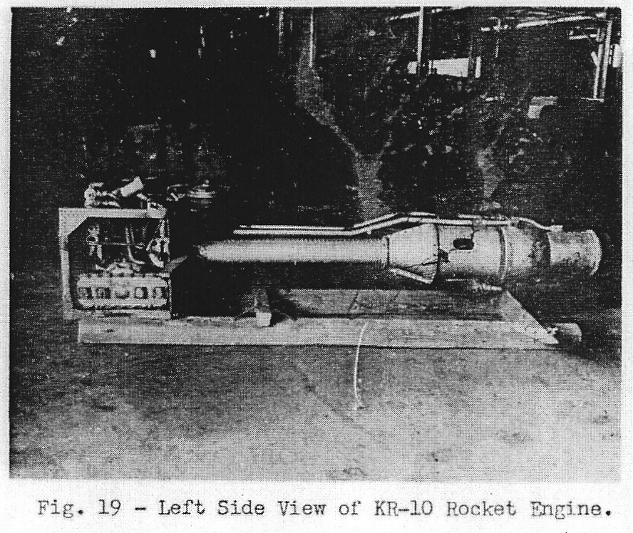
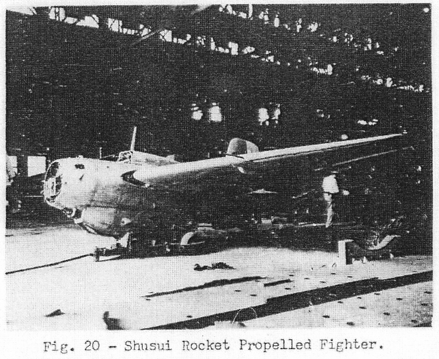
The KR-10 is apparently a copy of the German Walther R-211 rocket engine used in the ME 163. (Figures 18 and 19). The KR-10 is installed in the Shusui which is very similar to the ME 163. (Figure 20). German sources state that complete ME 163 plans were turned over to the Japanese about a year before their surrender. The Japanese experienced the same difficulties in producing “T-Stuff” (hydrogen peroxide) and “C-Stoff” (hydrazin-methanol-catalyst) fuels as did the Germans. The engines were put into production in July 1945. Shusui made one flight in July 1945 but crashed due to probable fuel feed failure.
The KR-10 develops 3300 lbs. thrust for 4 minutes and weighs 375 lbs. A description of this engine will not be made here due to the similarity of KR-10 to the German engine.
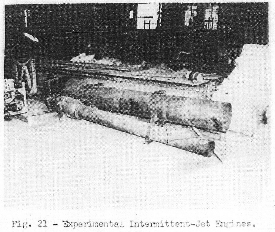
The KA-10 intermittent-jet is also borrowed from the German designs, namely the Argus As 0014 “V-1” engine. (Figure 21). The only departure in design from the As 0014 is the expansion chamber aft of the valve matrix. 288 fuel nozzles are used in this matrix. 990 lbs. thrust were obtained on the test stand with a 2.6 lbs/hr-lb.thrust specific fuel consumption. The KA-10 was to be used in the Baika aircraft.
No information is available on the free piston compressor system other than it was destined for a large aircraft and the project was abandoned in August 1944.
C. Summary. –
Table I shows a tabulation of the various jet engines tried by the Japanese. It should be noted that information on these engines is derived from Japanese Naval sources. However, interrogation of German personnel revealed that of the Japanese technical officers sent to Germany, only those of the Navy were interested in jet development work. The Army group wanted production drawings solely. This same policy was reflected in Japanese conventional engines – Army engine research was on the whole poorer than that by the Navy.
Figures 1 to 21 show photographs of jet power plants taken in Japan. The Navy Department is arranging for test of one of the two Ne 20 turbo-jets recovered. This engine appears to be the most promising of those developed by the Japs.
It is believed that gasoline and pine-root distillate were used as fuel for turbo-jets. Germany had to resort to 50/50 diesel fuel and kerosene due to gasoline shortage and resultant specific fuel consumptions were higher.
Electric furnace alloy steels with no Nickel were being developed by the Air Technical Arsenal for turbines. These were specified to have a creep limit of 20 Kg/sq. mm at 600°C. The steel developed was a Mn-Cr-V allow (I-309) with .22% C, 16% Mn, 11% Cr and .7% V. A nitrogenized alloy of .15% X, 14% Mn, 11% Cr, .7% V and .15% N was anticipated to up the temperature limit above to 650°C. A flux coated welding rod using I-309 was developed for welding of blades and disks.
The Japanese jet program can well be summarized by the expression “too little, too late”.
TABLE I
| (1) TURBO-JETS | ||||||||||
|---|---|---|---|---|---|---|---|---|---|---|
| AGENCY | ENGINE | STATUS (1) | DATE 19__ | ARRANGEMENT (2) | WEIGHT lbs. | THRUST lbs. | RPM | SFC lb/hr-lb | LENGTH inches | DIAMETER inches |
| Air Technical Arsenal (ATA) | No name | e | 42-43 | r-0c-a | ||||||
| TR-10 | e | 43-44 | r-0c-a | 770 | ||||||
| TR-12 | e | 43-44 | 4ar-0c-a | |||||||
| TR-12B | e | 44-45 | 4ar-0c-a | 700 | ||||||
| TR-30 | e | 43-44 | 4ar-0c-a | |||||||
| Ne-20 | s | 44-45 | 8a-0c-a | 1000 | 1100 | 11000 | 1.36 | 106.5 | 24.4 | |
| Ishikawajima | Ne 140 | p | 44 | axial compressor | ||||||
| Ne 130 | e | 44-45 | axial compressor | 1980 | 1980 | 9000 | 1.28 | 151.5 | 33.4 | |
| GTPR | p | 39-44 | P-12a-0c-5a | 5500 | 5000 bhp 373 mph | 5000 | 216 | 31.5 | ||
| Hitachi | Ne 230 | e | 44-45 | axial compressor | 1920 | 1950 | 8100 | 1.33 | 135 | 35.9×30 |
| Mitsubishi | Ne 330 | e | 44-45 | axial compressor | 2640 | 2860 | 7600 | 1.40 | 158 | 46.5×34.6 |
| (2) CAMPINI ENGINES | ||||||||||
| ATA | TSU-11 | s | 42-45 | engine-compressor | 440 | 440 | 3000 eng. 9000 comp. | 4.3 | 86.7 | 25.2 |
| Hitachi | MTPR | p | 42-44 | engine turbo-jet | ||||||
| (3) ROCKET ENGINES | ||||||||||
| ATA | KR-10 | s | 44-45 | bi-fuel rocket | 375 | 3300 | Pump 14500 | 2.1 | 98.5 | 35.4×25.6 |
| (4) INTERMITTENT JETS | ||||||||||
| ATA | KA-10 | e | 44-45 | Argus type | 330 | 990 | 2.6 | 146 | 22.8 | |
e- experimental
s- series
p- projected
(2) Arrangement: reading from left to right (direction of air flow), p – propeller, r- radial stage, a – axial stage, 12a – twelve axial stages, 0c – annular combustion chamber.
D. The Ne 20. –
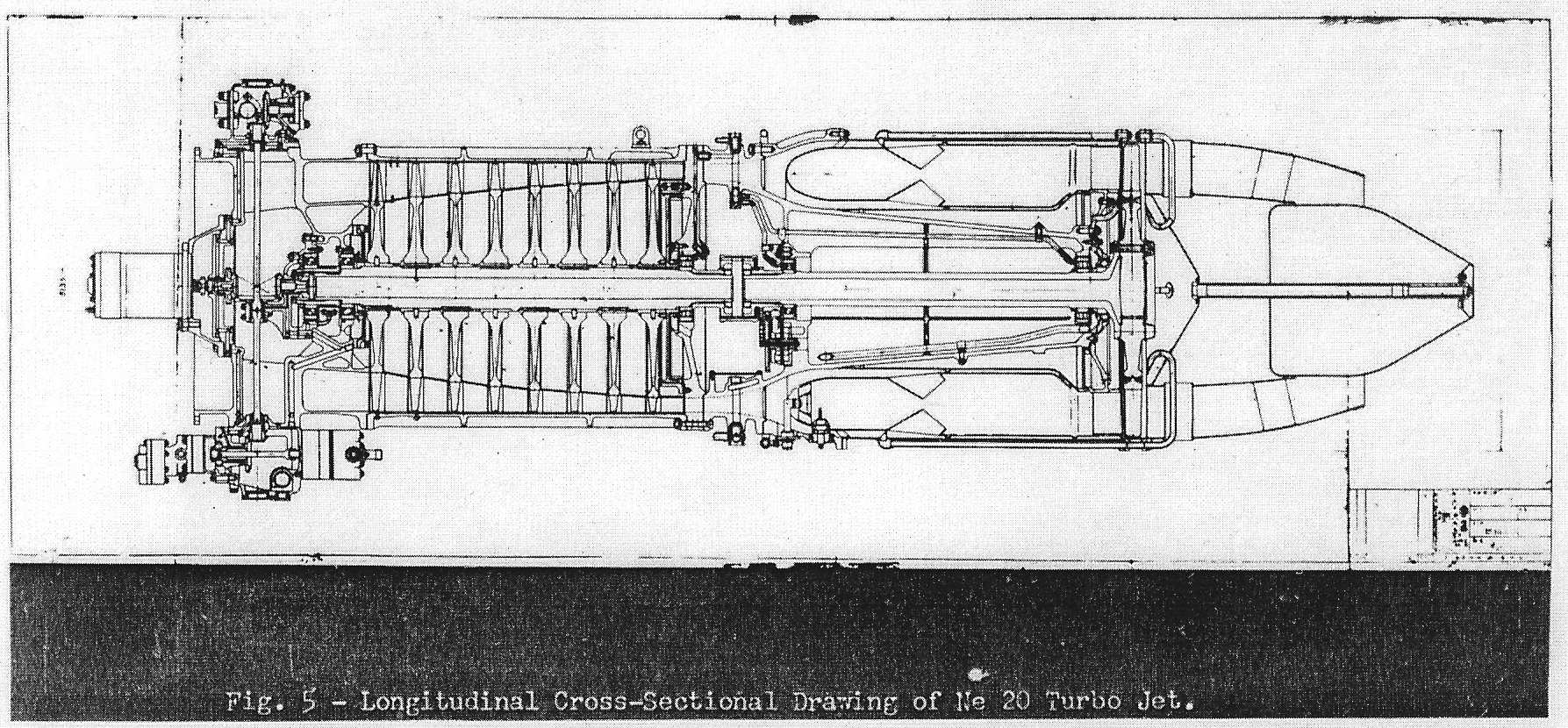
Development of the Ne 20 was carried out by the Naval Air Technical Arsenal. The design is based on the German BMW 003 engine and began in May 1944 upon the receipt of BMW 003 prints. The Ne 20 is about three-fourths the size of the 003. Two Ne 20’s were installed in Kikka and flight tested in early August 1945. The first flight on 7 August 1945 was successful for a duration of 21 minutes. In the second flight on 12 August the plane crashed in the sea on take-off due to pilot error (presumably). Twenty-one engines were constructed, nine at the Air Technical Arsenal and twelve at the Yokosuka Navy Yard. Production was scheduled to start at this latter agency in late summer 1945. Photographs of the Ne 20 are shown in figures 1 to 4 and drawings in Figures 5 to 7.
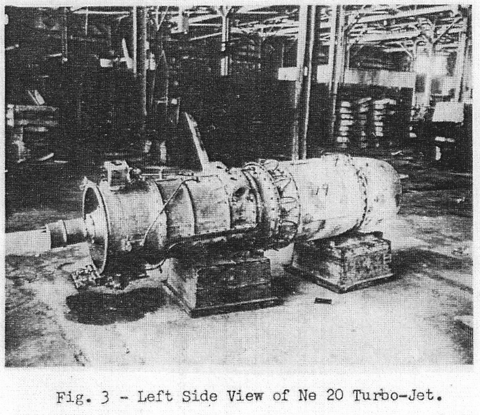
The Ne 20 is 106.5 inches long, 24.4 inches in diameter and 32 inches over the accessories. The dry weighs is 1000 lbs. The static thrust is given as from 1050 to 1100 lbs. at 11000 rpm and 1.36 lbs/hr-lb.thrust specific fuel consumption. 1100 lbs. thrusts is believed to be low in relation to the engine size and mass flow of 31 lbs/sec. 1300 lbs. thrust could probably have been realized from a more fully developed Ne 20. It should be noted, however, that the Japanese had virtually no back-log of information on high temperature materials. Japanese turbo-superchargers were only in the experimental stage and were largely based on German and captured U.S. equipment. The nozzle box temperature of the Ne 20 is listed as 1300-1380°F. which is somewhat lower than present U.S. and British turbo-jets.
An eight stage axial compressor is employed (the 003 has seven stages). The compressor rotor has a constant O.D. of 18.7 inches and is 21.3 inches long. Approximate rotor blade heights by stages are:
| Stage | Height | Stage | Height |
|---|---|---|---|
| 1 | 2.9″ | 5 | 1.7″ |
| 2 | 2.5″ | 6 | 1.5″ |
| 3 | 2.2″ | 7 | 1.3″ |
| 4 | 1.9″ | 8 | 1.1″ |
The means of rotor blade attachment is not known except that blades are tongued into peripherial grooves in the rotor disks. The first two compressor stages each have 28 blades. The number of blades for succeeding stages is not known.
Compressor rotor disks are apparently of aluminum alloy, shrunk and pinned on steel sleeves. These sleeves in turn act as spacers and are keyed to the compressor shaft. A shoulder is machined on the shaft between the fourth and fifth stages and the rotor discs are assembled from either end against this shoulder.
Labyrinth seals are employed at the forward and after end of the compressor rotor. A balance line is observed on each side of the engine apparently connected to these seals.
The combustion chamber is of the BMW type, being annular in design, using 12 BMW 003 burners and having sandwich mixers. The 003 has 16 of these burners. In scaling down the BMW chamber it is evident that the Japs used the same size burners but just three-fourths as many, thus eliminating additional experimentation by retaining the same flame length, airflow characteristics, etc.
The temperature of combustion is 2200°F, the nozzle box temperature 1300-1380°F, and the tail pipe temperature is 1020-1080°F.
The turbine is single stage axial flow and has solid blades. The turbine diameter is 22.1 inches and effective blade height is approximately 3.6 inches. Blades are tongued into the turbine disk. The turbine wheel is overhung on the turbine shaft and is joined to a face coupling on the shaft through bolts.
The rotating masses are supported in a similar fashion to that of the 003. Compressor thrust is taken by a single-row ball bearing forward. The after end of the compressor shaft is supported by a single-row roller bearing. The turbine shaft is supported by a single-row ball bearing forward taking end thrust and a single-row bearing aft (just forward of the turbine wheel). The two turbine bearings are pressure oiled from the main oil pump and scavenged by a pump mounted on the forward end of the turbine shaft. The turbine shaft extends through the combustion chamber. Both the turbine and compressor shafts are necked down to receive a short, internally splined, sleeve coupling.
The distance between turbine bearing centers is 21.8 inches, compressor bearing centers 25.3 inches and the distance between the after compressor bearing and the forward turbine bearing is 7.7 inches.
The tail cone is adjustable on the ground for variation in operating conditions and the total travel of the cone is 4 inches. Minimum exhaust area is estimated to be 105 sq. in. in the extended position and 180 sq. in. in the retracted position.
The engine housing from the primary combustion chamber section, forward appears to be made from light alloy castings and the housing aft of this section is apparently constructed of welded sheet ferritic metal. 18-8 stainless steel was tried for the combustion chamber but later aluminum dipped mild-steel was used here.
Accessories are driven from two vertical tower shafts connected to a single bevel gear. This gear is driven by a bevel gear on the compressor shaft.
Starting is effected by an electric started mounted within the compressor spinner and drives through double 4:1 reduction spur gears to a bevel gear. This bevel gear drives the engine through the accessory drive bevel gear. The engine is usually started at 1500 rpm. Japanese sources state that the starter is capable of turning the engine over at 6000 rpm which is 24000 rpm starter speed and is considered dubious. The Japanese perfected 1500 rpm a.c. and 10000 rpm d.c. motors of about 1 bhp but none at higher rpms.
Accessories are geared into the top and bottom of the vertical tower shafts. For the top accessories a gear box only is shown and it is believed that these take-offs are provided for generator, vacuum pump, tachometer and other aircraft accessories. The bottom group of accessories is presumed to consist of pressure oil pumps, dual fuel pump, governor and booster coil. On the lower right side of the engine is what appears to be a vapor separator of the pendulum type. An oil tank is located concentrically below the engine entry duct.
The engine is mounted by means of two vertical pads cast on either side of the compressor housing centering over the eight stator stage. The compressor housing is parted on a horizontal plane. Stator ring halves are bolted to the compressor casting on each side of the parting surface.
In all the Ne 20 appears to be a fairly well and simply designed turbo-jet. The BMW 003 was probably the best of the smaller German turbo-jets and the Japanese apparently didn’t sacrifice any of the 003’s good features. It should be noted that a Japanese plane with two Ne 20’s would have equivalent performance to a German plane with two 003’s due to the light construction employed by the Japanese in their aircraft.
E. Illustration Index –
Figure View
- Front right quarter Ne 20
- Rear left quarter Ne 20
- Left side Ne 20
- Right side Ne 20
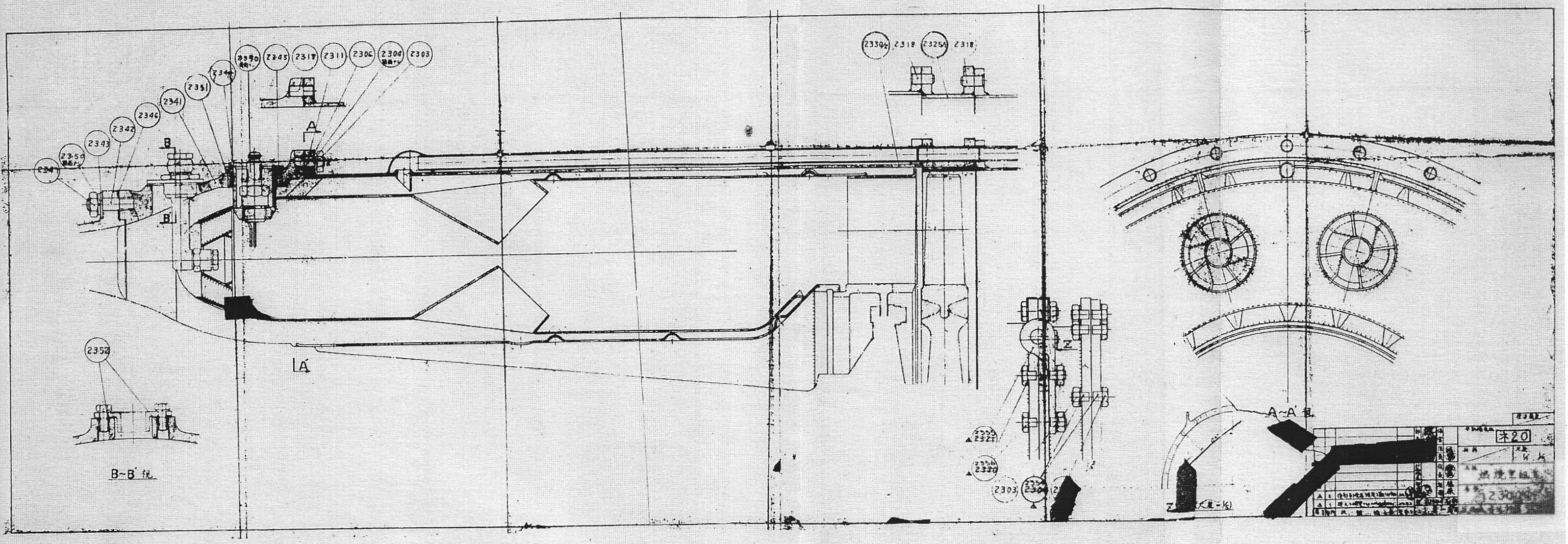
- Longitudinal crossectional drawing Ne 20
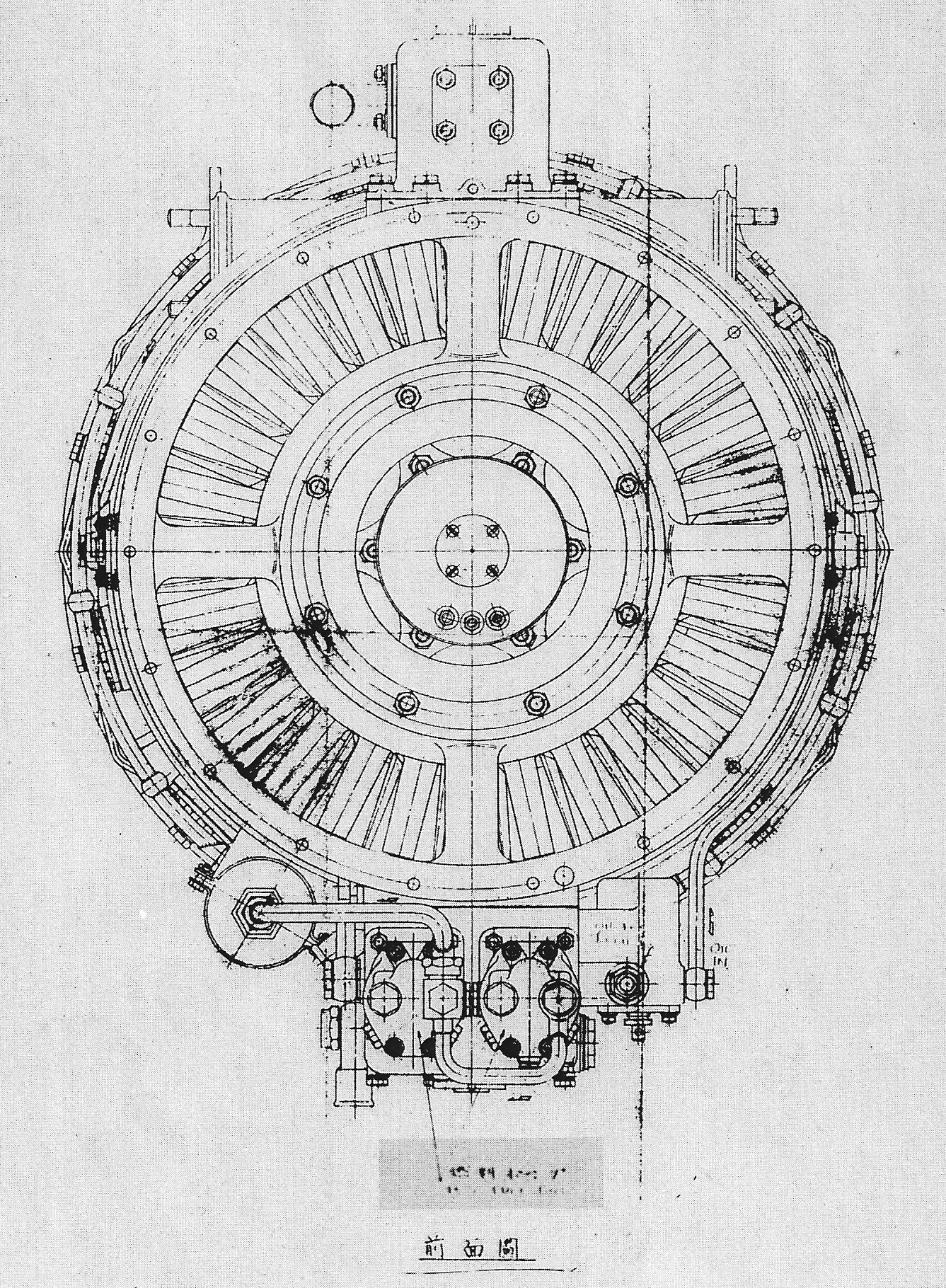
- Forward end drawing Ne 20
- Combustion chamber detail drawings Ne 20
- Nose section of Oka 43 mock-up
- Oka 43 and Ne 20 mock-ups
- Left side TR-30
- TR-30 mock-up
- Compressor mock-up of GTPR engine
- Turbine and tail pipe mock-up of GTPR engine
- Two combustion chambers and shaft housing of GTPR engine
- TR-12B turbo jet engines
- Hatsukaze engine installation in Oka 22.
- Rear of Oka 22
- Rear of KR-10 rocket engine
- Left side of KR-10 rocket engine
- Shusui rocket fighter.
- Experimental intermittent-jet engines
[ Figures 12 – 16 are sadly missing, all pictures of GTPR ]